ANSI FLANGE
ANSI (American National Standards Institute) flanges are standardized piping components essential for connecting metal tube pipes, valves, pumps, and other equipment to create secure and efficient systems. Built to stringent ANSI specifications, these different flange types ensure compatibility and reliability across a wide range of applications and industries, including oil and gas, chemical processing, water treatment, and power generation.ANSI flanges are widely used to connect different sections of pipes, ensuring a reliable flow of materials in industrial applications. They are ideal for isolating parts of the piping system during maintenance and using blind flanges to stop flow when needed. Weld neck flanges are often chosen for high-pressure applications due to their strength and durability. Corrosion-resistant materials also make ANSI flanges ideal for systems handling hazardous or corrosive substances, enhancing safety and system longevity.
ANSI vs DIN
When selecting the right flange for industrial applications, understanding the differences between ANSI Flange and DIN Flange is crucial. These two standards dominate piping systems worldwide, but their specifications, pressure ratings, and applications differ significantly. Whether you are working in the oil and gas industry, chemical processing, or water treatment, choosing the correct flange ensures safety, compatibility, and efficiency.
What is an ANSI Flange
The ANSI Flange follows the standards set by the American National Standards Institute (ANSI), primarily ASME B16.5 and ASME B16.47. These flanges are widely used in North America and are designed for high-pressure and high-temperature applications. ANSI flanges are categorized by class ratings, such as Class 150, 300, 600, 900, 1500, and 2500, indicating their pressure-handling capabilities. Their standardized dimensions ensure interchangeability and ease of installation in industrial piping systems.
What is a DIN Flange?
The DIN Flanges is based on the Deutsches Institut für Normung (DIN) standards, which are commonly used in Europe and many parts of Asia. DIN flanges follow the EN 1092-1 specification, with pressure ratings denoted as PN (Pressure Nominal), such as PN6, PN10, PN16, PN25, PN40, and higher. These flanges offer high precision and are widely adopted in industries requiring metric-based engineering systems.
ANSI Flange vs. DIN Flange: Key Differences
Measurement System: ANSI flanges use the imperial system (inches and PSI), while DIN flanges use the metric system (mm and bar).
Pressure Ratings: ANSI flanges are classified by class (e.g., Class 150, 300), whereas DIN flanges are rated in PN values.
Bolt Hole Arrangement: The number, size, and spacing of bolt holes differ between the two standards, making them incompatible without adapters.
Applications: ANSI flanges are prevalent in American-based industries, while DIN flanges are commonly used in European engineering projects.
Which Flange Should You Choose?
Your choice between an ANSI Flange and a DIN Flange depends on your project’s location, existing piping standards, and pressure requirements. If your system follows North American standards, ANSI flanges are ideal. If you work with European or metric-based systems, DIN flanges ensure compatibility.
For businesses operating globally, understanding these differences helps in selecting the right components and avoiding costly mismatches. Whether you need an ANSI Flange or a DIN Flange, always ensure compliance with industry standards for a secure and efficient piping system.
ANSI Flange Types
When it comes to industrial piping systems, selecting the right ANSI Flange is critical for ensuring safety, durability, and efficiency. At Yulong, we offer a comprehensive range of ANSI flanges designed to meet diverse operational requirements, from high-pressure environments to corrosive conditions.
Common ANSI Flange Types
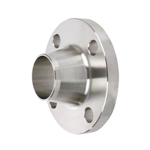
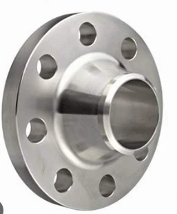
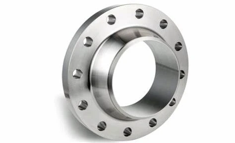
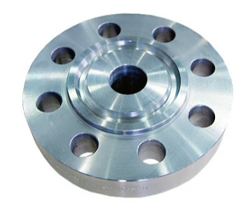
Weld Neck Flange – Ideal for high-pressure applications, this flange features a long tapered hub that enhances structural integrity and minimizes stress concentration. Yulong’s precision-engineered weld neck flanges provide superior sealing and durability.
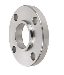
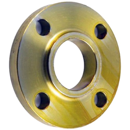
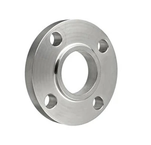
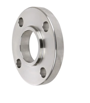
Slip-On Flange – This flange is easy to install and cost-effective and is commonly used in low-pressure systems. Yulong’s slip-on flanges ensure a secure fit, reducing the risk of leakage while maintaining efficiency.
Socket Weld Flange – Designed for small-diameter, high-pressure pipelines, this flange provides a smooth bore and excellent flow characteristics. Yulong manufactures socket weld flanges with high-strength materials for long-lasting performance.
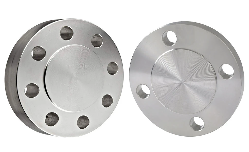
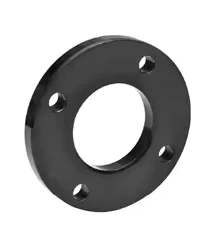
Blind Flange – Used to seal off pipelines, blind flanges are essential for system maintenance and pressure testing. Yulong’s blind flanges are built to withstand extreme conditions, ensuring operational reliability.
Threaded Flange – Ideal for non-welded applications, these flanges are perfect for systems requiring easy disassembly. Yulong’s threaded flanges offer precision threading for leak-proof connections.
Why Choose Yulong ANSI Flanges?
At Yulong, we prioritize quality, precision, and industry compliance. Our ANSI Flange solutions are crafted from premium materials, ensuring superior performance in various industrial sectors, including oil & gas, petrochemicals, and water treatment.
Upgrade your piping system with Yulong’s ANSI flanges, which are trusted by industry leaders worldwide. Contact us today to find the perfect flange for your needs!
The Role of ANSI Flanges in Corrosion Resistance and Leak Prevention
ANSI (American National Standards Institute) flanges play a crucial role in industrial piping systems by ensuring robust connections between pipes, valves, and other essential equipment. With corrosion resistance and leak prevention being primary concerns in these systems, ANSI flanges have been designed to address these challenges, particularly in industries such as oil and gas, chemical processing, and water treatment.
Corrosion Resistance in ANSI Flanges
Corrosion is a persistent issue in industrial pipelines, especially when they carry corrosive fluids or operate in harsh environmental conditions. ANSI flanges are made from high-quality materials, including stainless steel, carbon steel, and alloys like nickel or chrome, which resist degradation over time. Stainless steel ANSI flanges, in particular, provide excellent resistance to rust and chemical attack, making them ideal for corrosive applications. This corrosion-resistant design ensures that piping systems maintain their integrity over time, reducing the need for frequent replacements or costly repairs.
Leak Prevention About ANSI Flanges
Leak prevention is essential for maintaining system efficiency and safety, especially under high pressure or in hazardous applications. ANSI flanges are manufactured with precise machining and high-quality surface finishes that contribute to a secure, tight seal when installed with compatible gaskets. Weld neck and socket weld flanges are especially valued for high-pressure environments, as their design minimizes the risk of leaks. This secure seal not only preserves system efficiency by preventing fluid loss but also protects the surrounding environment and reduces the risk of exposure to hazardous substances.
What is the Difference Between ASME and ANSI Flanges?
ASME (American Society of Mechanical Engineers) and ANSI (American National Standards Institute) flanges are both essential components in piping systems, but they serve different purposes and conform to different standards. Understanding the distinction between ASME and ANSI flanges can help in selecting the correct flange for specific applications.
1. Governing Standards of ANSI Flanges
ASME flanges are governed by the ASME B16.5 standard, which sets the guidelines for pressure, temperature, material specifications, and dimensions for flanges in industrial applications. ASME standards primarily focus on safety and performance, ensuring that the flange can handle the designated pressure and temperature in various environments. ANSI, on the other hand, does not develop its own flange standards but instead accredits organizations (like ASME) to create and publish standards that meet ANSI’s criteria. Thus, ANSI serves as an overarching body that ensures quality and consistency, while ASME provides the technical guidelines.
2. Applications and Pressure Ratings of ANSI Flanges
ASME flanges are specifically designed for high-pressure applications and are used in industries such as oil and gas, petrochemicals, and power generation. These flanges typically have pressure ratings that range from Class 150 to Class 2500, accommodating a wide spectrum of pressure requirements. While ANSI is involved in setting quality benchmarks, it does not directly specify the pressure ratings; this is determined by the ASME B16.5 standard.
3. Dimensional Compatibility of ANSI Flanges
While ASME and ANSI flanges are often used interchangeably, it’s important to check that both have compatible dimensions and pressure classes to ensure a proper fit. ASME provides detailed specifications on bolt patterns, flange faces, and sizes, which help engineers match flanges precisely to pipes and other equipment.
ANSI Flange FAQs
How Do ANSI Flanges Differ from Other Flanges? |
| ANSI flanges follow specific dimensional and pressure ratings based on ANSI/ASME B16.5 standards, ensuring compatibility and safety in industrial applications. Other flange standards, such as DIN or JIS, have different size and pressure specifications. |
What Materials Are ANSI Flanges Made From? |
| ANSI flanges are available in materials like carbon steel, stainless steel, and alloy steel, depending on the application’s requirements for pressure, temperature, and corrosion resistance. |
Why Choose Yulong ANSI Flanges? |
| Yulong offers high-quality ANSI flanges manufactured with precision and durability, ensuring reliable performance in the oil & gas, chemical, and water treatment industries. Need expert guidance? Contact Yulong today for premium ANSI flange solutions! |
What Pressure Ratings Do ANSI Flanges Have? |
| ANSI flanges are available in various pressure classes, including 150, 300, 600, 900, 1500, and 2500, to accommodate different industrial needs. The higher the class, the greater the pressure it can withstand. |
ANSI Flange Dimensions
| SLIP-ON | |||||||||||||||
| WELDING NECK | |||||||||||||||
| SOCKET WELDING | |||||||||||||||
| THREADED | |||||||||||||||
| LAP JOINT | |||||||||||||||
| BLIND | |||||||||||||||
| CLASS 150 FLANGES | |||||||||||||||
| ANSI B16.5 FORGED FLANGES | |||||||||||||||
| Unit: mm |
| Nominal បំពង់ Size |
Outside Diam. |
Diam. at Base of Hub |
O.D of | Thick- ness |
BORE | LENGTH THRU HUB | Diam, of Hub at Bevel |
Radius of Fillet |
Thread Length |
||||
| Raised Face |
ការផ្សារដែក Neck Socket ការផ្សារដែក |
Slip-on Socket ការផ្សារដែក |
Lap Joint |
ការផ្សារដែក Neck |
Sip-on Threaded Socket ការផ្សារដែក |
Lap Joint |
|||||||
| D | X | G | t | B1 | B2 | B3 | T1 | T2 T3 | A | R | Q | ||
| 1/2 | 89 | 30.2 | 35.1 | 11.2 | 15.7 | 22.4 | 22.9 | 47.8 | 15.7 | 15.7 | 21.3 | 3.0 | 15.7 |
| 3/4 | 99 | 38.1 | 42.9 | 12.7 | 20.8 | 27.7 | 28.2 | 52.3 | 15.7 | 15.7 | 26.7 | 3.0 | 15.7 |
| 1 | 108 | 49.3 | 50.8 | 14.2 | 26.7 | 34.5 | 35.1 | 55.6 | 17.5 | 17.5 | 33.5 | 3.0 | 17.5 |
| 11/4 | 117 | 58.7 | 63.5 | 15.7 | 35.1 | 43.2 | 43.7 | 57.2 | 20.6 | 20.6 | 42.2 | 4.8 | 20.6 |
| 11/2 | 127 | 65.0 | 73.2 | 17.5 | 40.9 | 49.5 | 50.0 | 62.0 | 22.4 | 22.4 | 48.3 | 6.4 | 22.4 |
| 2 | 152 | 77.7 | 91.9 | 19.1 | 52.6 | 62.0 | 62.5 | 63.5 | 25.4 | 25.4 | 60.5 | 7.9 | 25.4 |
| 21/2 | 178 | 90.4 | 104.6 | 22.4 | 62.7 | 74.7 | 75.4 | 69.9 | 28.4 28.4 |
28.4 28.4 |
73.2 | 7.9 | 28.4 |
| 3 | 191 | 108.0 | 127.0 | 23.9 | 78.0 | 90.7 | 91.4 | 69.9 | 30.2 | 30.2 | 88.9 | 9.7 | 30.2 |
| 3 1/2 | 216 | 122.2 | 139.7 | 23.9 | 90.2 | 103.4 | 104.1 | 71.4 | 31.8 | 31.8 | 101.6 | 9.7 | 31.8 |
| 4 | 229 | 134.9 | 157.2 | 23.9 | 102.4 | 116.1 | 116.8 | 76.2 | 33.3 | 33.3 | 114.3 | 11.2 | 33.3 |
| 5 | 254 | 163.6 | 185.7 | 23.9 | 128.3 | 143.8 | 144.5 | 88.9 | 36.6 | 36.6 | 141.2 | 11.2 | 36.6 |
| 6 | 279 | 192.0 | 215.9 | 25.4 | 154.2 | 170.7 | 171.5 | 88.9 | 39.6 | 39.6 | 168.4 | 12.7 | 39.6 |
| 8 | 343 | 246.1 | 269.7 | 28.4 | 202.7 | 221.5 | 222.3 | 101.6 | 44.5 | 44.5 | 219.2 | 12.7 | 44.5 |
| 10 | 406 | 304.8 | 323.9 | 30.2 | 254.5 | 276.4 | 277.4 | 101.6 | 49.3 | 49.3 | 273.1 | 12.7 | 49.3 |
| 12 | 483 | 365.3 | 381.0 | 31.8 | 304.8 | 327.2 | 328.2 | 114.3 | 55.6 | 55.6 | 323.9 | 12.7 | 55.6 |
| 14 | 533 | 400.1 | 412.8 | 35.1 | 336.6 | 359.2 | 360.2 | 127.0 | 57.2 | 79.2 | 355.6 | 12.7 | 57.2 |
| 16 | 597 | 457.2 | 469.9 | 36.6 | 387.4 | 410.5 | 411.2 | 127.0 | 63.5 | 87.4 | 406.4 | 12.7 | 63.5 |
| 18 | 635 | 505.0 | 533.4 | 39.6 | 438.2 | 461.8 | 462.3 | 139.7 | 68.3 | 96.8 | 457.2 | 12.7 | 68.3 |
| 20 | 699 | 558.8 | 584.2 | 42.9 | 489.0 | 513.1 | 514.4 | 144.5 | 73.2 | 103.1 | 508.0 | 12.7 | 73.2 |
| 24 | 813 | 663.4 | 692.2 | 47.8 | 590.6 | 616.0 | 616.0 | 152.4 | 82.6 | 111.3 | 609.6 | 12.7 | 82.6 |
| Nominal បំពង់ Size |
Depth of Socket |
DRILLING | BOLTING | APPROXIMATE WEIGHT | |||||||||||
| Bolt Circle Diam |
Number of Holes |
Diam of Holes |
Diam of Bolts (inch) |
Machine Bot Length |
Stud Bolt Length |
ការផ្សារដែក Neck |
Slip-on and Threaded |
Lan | Blind | Socket ការផ្សារដែក |
|||||
| Y | Raised Face |
Raised Face |
Ring Joint |
SCH40 | SCH80 | SCH160 | |||||||||
| 1/2 | 9.7 | 60.5 | 4 | 15.7 | 1/2 | 50.8 | 57.2 | 0.60 | 0.60 | 0.60 | 0.41 | 0.40 | 0.43 | 0.41 | |
| 3/4 | 11.2 | 69.9 | 4 | 15.7 | 1/2 | 50.8 | 63.5 | 0.90 | 0.90 | 0.90 | 0.58 | 0.58 | 0.63 | 0.58 | |
| 1 | 12.7 | 79.2 | 4 | 15.7 | 1/2 | 57.2 | 63.5 | 76.2 | 1.14 | 1.18 | 1.24 | 0.80 | 0.80 | 0.89 | 0.80 |
| 11/4 | 14.2 | 88.9 | 4 | 15.7 | 1/2 | 57.2 | 69.9 | 82.6 | 1.41 | 1.48 | 1.54 | 1.07 | 1.07 | 1.20 | 1.07 |
| 11/2 | 15.7 | 98.6 | 4 | 15.7 | 1/2 | 63.5 | 69.9 | 82.6 | 1.81 | 1.90 | 2.01 | 1.37 | 1.37 | 1.58 | 1.37 |
| 2 | 17.5 | 120.7 | 4 | 19.1 | 5/8 | 69.9 | 82.6 | 95.3 | 2.72 | 2.84 | 3.07 | 2.21 | 2.21 | 2.39 | 2.21 |
| 2 1/2 | 19.1 | 139.7 | 4 | 19.1 | 5/8 | 76.2 | 88.9 | 101.6 | 4.45 | 4.70 | 4.98 | 3.32 | 3.34 | 4.07 | 3.32 |
| 3 | 20.6 | 152.4 | 4 | 19.1 | 5/8 | 76.2 | 88.9 | 101.6 | 5.22 | 5.54 | 5.90 | 3.83 | 3.83 | 4.92 | 3.83 |
| 3 1/2 | 22.4 | 177.8 | 8 | 19.1 | 5/8 | 76.2 | 88.9 | 101.6 | 6.40 | 6.76 | 7.46 | 5.20 | 5.2 | 5.9 | 5.2 |
| 4 | 23.9 | 190.5 | 8 | 19.1 | 5/8 | 76.2 | 88.9 | 101.6 | 7.49 | 7.96 | 8.90 | 5.4 | 5.4 | 7.13 | 5.9 |
| 5 | 23.9 | 215.9 | 8 | 22.4 | 3/4 | 82.6 | 95.3 | 108.0 | 9.53 | 10.54 | 12.04 | 626 | 6.26 | 8.72 | 6.80 |
| 6 | 26.9 | 241.3 | 8 | 22.4 | 3/4 | 82.6 | 101.6 | 114.3 | 11.80 | 13.12 | 15.11 | 7.50 | 7.5 | 11.4 | 8.60 |
| 8 | 31.8 | 298.5 | 8 | 22.4 | 3/4 | 88.9 | 108.0 | 120.7 | 19.10 | 21.34 | 25.84 | 12.30 | 12.4 | 20.1 | 13.60 |
| 10 | 33.3 | 362.0 | 12 | 25.4 | 7/8 | 101.6 | 114.3 | 127.0 | 24.50 | 28.85 | 35.74 | 17.10 | 17.1 | 28.70 | 19.50 |
| 12 | 39.6 | 431.8 | 12 | 25.4 | 7/8 | 101.6 | 120.7 | 133.4 | 39.90 | 46.80 | 58.01 | 26.50 | 26.50 | 43.80 | 29.10 |
| 14 | 41.4 | 476.3 | 12 | 28.4 | 1 | 114.3 | 133.4 | 146.1 | 51.80 | 62.58 | 77.60 | 34.50 | 38.50 | 58.20 | 40.90 |
| 16 | 44.5 | 539.8 | 16 | 28.4 | 1 | 114.3 | 133.4 | 146.1 | 64.50 | 79.42 | 98.82 | 45.50 | 51.20 | 77.40 | 44.50 |
| 18 | 49.3 | 577.9 | 16 | 31.8 | 1 1/8 | 127.0 | 146.1 | 158.8 | 74.90 | 97.63 | 124.32 | 48.50 | 55.70 | 94.00 | 59.00 |
| 20 | 54.1 | 635.0 | 20 | 31.8 | 1 1/8 | 139.7 | 158.8 | 171.5 | 89.40 | 120.44 | 154.18 | 61.80 | 70.20 | 122.70 | 74.90 |
| 24 | 63.5 | 749.3 | 20 | 35.1 | 1 1/4 | 152.4 | 171.5 | 184.2 | 121.70 | 169.37 | 223.92 | 87.70 | 98.70 | 187.00 | 99.90 |
| SLIP-ON | |||||||||||||||
| WELDING NECK | |||||||||||||||
| SOCKET WELDING | |||||||||||||||
| THREADED | |||||||||||||||
| LAP JOINT | |||||||||||||||
| BLIND | |||||||||||||||
| CLASS 300 FLANGES | |||||||||||||||
| ANSI B16.5 FORGED FLANGES | |||||||||||||||
| Unit: mm |
| Nominal បំពង់ Size |
Outside Diam. |
Diam. at Base of Hub |
O.D of | Thick- ness |
BORE | LENGTH THRU HUB | Diam, of Hub at Bevel |
Radius of Fillet |
Thread Length |
|||||
| Raised Face |
ការផ្សារដែក Nock Socket ការផ្សារដែក |
Slip-on Socket ការផ្សារដែក |
Lap Joint |
Counter Bore Threaded Min. |
ការផ្សារដែក Neck |
Slip-on Threaded Socket ការផ្សារដែក |
Lap Joint |
|||||||
| D | X | G | 1 | B1 | B2 | B3 | B | T1 | T2 | T3 | A | R | Q | |
| 1/2 | 95 | 38.1 | 35.1 | 14.2 | 15.7 | 22.4 | 22.9 | 23.6 | 52.3 | 22.4 | 22.4 | 21.3 | 3.0 | 15.7 |
| 3/4 | 117 | 47.8 | 42.9 | 15.7 | 20.8 | 27.7 | 28.2 | 29.0 | 57.2 | 25.4 | 25.4 | 26.7 | 3.0 | 15.7 |
| 1 | 124 | 53.8 | 50.8 | 17.5 | 26.7 | 34.5 | 35.1 | 35.8 | 62.0 | 26.9 | 26.9 | 33.5 | 3.0 | 17.5 |
| 1 1/4 | 133 | 63.5 | 63.5 | 19.1 | 35.1 | 43.2 | 43.7 | 44.5 | 65.0 | 26.9 | 26.9 | 42.2 | 4.8 | 20.6 |
| 1 1/2 | 155 | 69.9 | 73.2 | 20.6 | 40.9 | 49.5 | 50.0 | 50.5 | 68.3 | 30.2 | 30.2 | 48.3 | 6.4 | 22.4 |
| 2 | 165 | 84.1 | 91.9 | 22.4 | 52.6 | 62.0 | 62.5 | 63.5 | 69.9 | 33.3 | 33.3 | 60.5 | 7.9 | 28.4 |
| 2 1/2 | 191 | 100.1 | 104.6 | 25.4 | 62.7 | 74.7 | 75.4 | 76.2 | 76.2 | 38.1 | 38.1 | 73.2 | 7.9 | 31.8 |
| 3 | 210 | 117.3 | 127.0 | 28.4 | 78.0 | 90.7 | 91.4 | 92.2 | 79.2 | 42.9 | 42.9 | 88.9 | 9.7 | 31.8 |
| 3 1/2 | 229 | 133.4 | 139.7 | 30.2 | 90.2 | 103.4 | 104.1 | 104.9 | 81.0 | 44.5 | 44.5 | 101.6 | 9.7 | 36.6 |
| 4 | 254 | 146.1 | 157.2 | 31.8 | 102.4 | 116.1 | 116.8 | 117.6 | 85.9 | 47.8 | 47.8 | 114.3 | 11.2 | 36.6 |
| 5 | 279 | 177.8 | 185.7 | 35.1 | 128.3 | 143.8 | 144.5 | 144.5 | 98.6 | 50.8 | 50.8 | 141.2 | 11.2 | 42.9 |
| 6 | 318 | 206.2 | 215.9 | 36.6 | 154.2 | 170.7 | 171.5 | 171.5 | 98.6 | 52.3 | 52.3 | 168.4 | 12.7 | 46.0 |
| 8 | 381 | 260.4 | 269.7 | 41.1 | 202.7 | 221.5 | 222.3 | 222.3 | 111.3 | 62.0 | 62.0 | 219.2 | 12.7 | 50.8 |
| 10 | 445 | 320.5 | 323.9 | 47.8 | 254.5 | 276.4 | 277.4 | 276.4 | 117.3 | 66.5 | 95.3 | 273.1 | 12.7 | 55.6 |
| 12 | 521 | 374.7 | 381.0 | 50.8 | 304.8 | 327.2 | 328.2 | 328.7 | 130.0 | 73.2 | 101.6 | 323.9 | 12.7 | 60.5 |
| 14 | 584 | 425.5 | 412.8 | 53.8 | 336.6 | 359.2 | 360.2 | 360.4 | 142.7 | 76.2 | 111.3 | 355.6 | 12.7 | 63.5 |
| 16 | 648 | 482.6 | 469.9 | 57.2 | 387.4 | 410.5 | 411.2 | 411.2 | 146.1 | 82.6 | 120.7 | 406.4 | 12.7 | 68.3 |
| 18 | 711 | 533.4 | 533.4 | 60.5 | 438.2 | 461.8 | 462.3 | 462.0 | 158.8 | 88.9 | 130.0 | 457.2 | 12.7 | 69.9 |
| 20 | 775 | 587.2 | 584.2 | 63.5 | 489.0 | 513.1 | 514.4 | 512.8 | 162.1 | 95.3 | 139.7 | 508.0 | 12.7 | 73.2 |
| 24 | 914 | 701.5 | 692.2 | 69.9 | 590.6 | 616.0 | 616.0 | 614.4 | 168.1 | 106.4 | 152.4 | 609.6 | 12.7 | 82.6 |
| Nominal បំពង់ Size |
Depth of Socket |
DRILLING | BOLTING | APPROXIMATE WEIGHT | |||||||||||
| Bolt Circle Diam |
Number of Holes |
Diam of Holes |
Diam of Bolts (inch) |
Machine Bot Length |
Stud Bolt Length |
ការផ្សារដែក Neck |
Slip-on and Threaded |
Lap Joint |
Blind | Socket ការផ្សារដែក |
|||||
| Y | Raised Face |
Raised Face |
Ring Joint |
SCH40 | SCH80 | SCH160 | |||||||||
| 1/2 | 9.7 | 66.5 | 4 | 15.7 | 1/2 | 57.2 | 63.5 | 76.2 | 0.91 | 0.91 | 0.91 | 0.63 | 0.63 | 0.63 | 0.63 |
| 3/4 | 11.2 | 82.6 | 4 | 19.1 | 5/8 | 63.5 | 76.2 | 88.9 | 1.36 | 1.36 | 1.36 | 1.16 | 1.16 | 1.15 | 1.16 |
| 1 | 12.7 | 88.9 | 4 | 19.1 | 5/8 | 63.5 | 76.2 | 88.9 | 1.82 | 1.87 | 1.93 | 1.39 | 1.39 | 1.4 | 1.37 |
| 1 1/4 | 14.2 | 98.6 | 4 | 19.1 | 5/8 | 69.9 | 82.6 | 95.3 | 2.27 | 2.35 | 2.41 | 1.75 | 1.75 | 1.88 | 1.75 |
| 1 1/2 | 15.7 | 114.3 | 4 | 22.4 | 3/4 | 76.2 | 88.9 | 101.6 | 3.18 | 3.28 | 3.40 | 2.53 | 2.53 | 2.65 | 2.47 |
| 2 | 17.5 | 127.0 | 8 | 19.1 | 5/8 | 76.2 | 88.9 | 101.6 | 3.36 | 3.49 | 3.75 | 2.90 | 2.91 | 3.22 | 2.90 |
| 2 1/2 | 19.1 | 149.4 | 8 | 22.4 | 3/4 | 82.6 | 101.6 | 114.3 | 5.45 | 5.72 | 6.02 | 4.17 | 2.88 | 4.8 | 4.17 |
| 3 | 20.6 | 168.1 | 8 | 22.4 | 3/4 | 88.9 | 108.0 | 120.7 | 8.17 | 8.54 | 8.94 | 5.92 | 4.20 5.87 |
6.89 | 5.92 |
| 3 1/2 | 22.4 | 184.2 | 8 | 22.4 | 3/4 | 95.3 | 108.0 | 127.0 | 8.90 | 9.31 | 10.10 | 7.72 | 7.72 | 8.90 | |
| 4 | 23.9 | 200.2 | 8 | 22.4 | 3/4 | 95.3 | 114.3 | 127.0 | 12.10 | 12.62 | 13.69 | 9.73 | 9.66 | 11.6 | |
| 5 | 23.9 | 235.0 | 8 | 22.4 | 3/4 | 108.0 | 120.7 | 133.4 | 16.30 | 17.42 | 19.08 | 12.10 | 12.1 | 15.6 | |
| 6 | 26.9 | 269.7 | 12 | 22.4 | 3/4 | 108.0 | 120.7 | 139.7 | 20.40 | 21.86 | 24.07 | 16.00 | 15.9 | 21.40 | |
| 8 | 31.8 | 330.2 | 12 | 25.4 | 7/8 | 120.7 | 139.7 | 152.4 | 31.30 | 33.75 | 38.69 | 23.90 | 23.80 | 34.10 | |
| 10 | 33.3 | 387.4 | 16 | 28.4 | 1 | 139.7 | 158.8 | 171.5 | 45.40 | 50.43 | 58.38 | 34.00 | 38.20 | 53.50 | |
| 12 | 39.6 | 450.9 | 16 | 31.8 | 1 1/8 | 146.1 | 171.5 | 184.2 | 64.50 | 72.35 | 85.10 | 49.10 | 54.90 | 78.30 | |
| 14 | 41.4 | 514.4 | 20 | 31.8 | 1 1/8 | 158.8 | 177.8 | 190.5 | 93.50 | 105.61 | 122.49 | 69.10 | 80.10 | 105.00 | |
| 16 | 44.5 | 571.5 | 20 | 35.1 | 1 1/4 | 165.1 | 190.5 | 203.2 | 113.10 | 130.25 | 152.56 | 88.90 | 103.90 | 138.60 | |
| 18 | 49.3 | 628.7 | 24 | 35.1 | 11/4 | 171.5 | 196.9 | 209.6 | 138.90 | 164.74 | 195.07 | 107.20 | 124.60 | 174.30 | |
| 20 | 54.1 | 685.8 | 24 | 35.1 | 11/4 | 184.2 | 203.2 | 222.3 | 167.50 | 202.32 | 240.17 | 132.90 | 154.40 | 220.40 | |
| 24 | 63.5 | 812.8 | 24 | 41.1 | 1 1/2 | 203.2 | 228.6 | 254.0 | 235.60 | 288.15 | 348.28 | 198.70 | 232.60 | 339.00 | |
| CLASS 600 FLANGES | |||||||||||||||
| ANSI B16.5 FORGED FLANGES | |||||||||||||||
| Unit: mm | |||||||||||||||
| Nominal បំពង់ Size |
Outside Diam. |
Diam. at Base of Hub |
O.D of Raised Face |
Thick- ness |
BORE | LENGTH THRU HUB | Diam. of Hub at Bevel |
Radius of Fillet | Thread Length | ||||||
| ការផ្សារដែក Neck Socket ការផ្សារដែក |
Slip-on Socket ការផ្សារដែក |
Lap Joint |
Counter Bore Min. |
ការផ្សារដែក Neck |
Sip-on Threaded Socket ការផ្សារដែក |
Lap Joint |
|||||||||
| D | X | G | t | See Note(1) To be specified by purchaser |
B2 | B3 | B | T1 | T2 | T3 | A | R | Q | ||
| 1/2 3/4 |
95 | 38.1 | 35.1 | 14.2 | 22.4 | 22.9 | 23.6 | 52.3 | 22.4 | 22.4 | 21.3 | 3.0 | 15.7 | ||
| 117 | 47.8 | 42.9 | 15.7 | 27.7 | 28.2 | 29.0 | 57.2 | 25.4 | 25.4 | 26.7 | 3.0 | 15.7 | |||
| 1 | 124 | 53.8 | 50.8 | 17.5 | 34.5 | 35.1 | 35.8 | 62.0 | 26.9 | 26.9 | 33.5 | 3.0 | 17.5 | ||
| 1 1/4 | 133 | 63.5 | 63.5 | 20.6 | 43.2 | 43.7 | 44.5 | 66.5 | 28.4 | 28.4 | 42.2 | 4.8 | 20.6 | ||
| 1 1/2 | 155 | 69.9 | 73.2 | 22.4 | 49.5 | 50.0 | 50.5 | 69.9 | 31.8 | 31.8 | 48.3 | 6.4 | 22.4 | ||
| 2 | 165 | 84.1 | 91.9 | 25.4 | 62.0 | 62.5 | 63.5 | 73.2 | 36.6 | 36.6 | 60.5 | 7.9 | 28.4 | ||
| 2 1/2 | 191 | 100.1 | 104.6 | 28.4 | 74.7 | 75.4 | 76.2 | 79.2 | 41.1 | 41.1 | 73.2 | 7.9 | 35.1 | ||
| 3 | 210 | 117.3 | 127.0 | 31.8 | 90.7 | 91.4 | 92.2 | 82.6 | 46.0 | 46.0 | 88.9 | 9.7 | 39.6 | ||
| 3 1/2 | 229 | 133.4 | 139.7 | 35.1 | 103.4 | 104.1 | 104.9 | 85.9 | 49.3 | 49.3 | 101.6 | 9.7 | 41.1 | ||
| 4 | 273 | 152.4 | 157.2 | 38.1 | 116.1 | 116.8 | 117.6 | 101.6 | 53.8 | 53.8 | 114.3 | 11.2 | 47.8 | ||
| 5 | 330 | 189.0 | 185.7 | 44.5 | 143.8 | 144.5 | 144.5 | 114.3 | 60.5 | 60.5 | 141.2 | 11.2 | 50.8 | ||
| 6 | 356 | 222.3 | 215.9 | 47.8 | 170.7 | 171.5 | 171.5 | 117.3 | 66.5 | 66.5 | 168.4 | 12.7 | 57.2 | ||
| 8 | 419 | 273.1 | 269.7 | 55.6 | 221.5 | 222.3 | 222.3 | 133.4 | 76.2 | 76.2 | 219.2 | 12.7 | 65.0 | ||
| 10 | 508 | 342.9 | 323.9 | 63.5 | 276.4 | 277.4 | 276.4 | 152.4 | 85.9 | 111.3 | 273.1 | 12.7 | 69.9 | ||
| 12 | 559 | 400.1 | 381.0 | 66.5 | 327.2 | 328.2 | 328.7 | 155.4 | 91.9 | 117.3 | 323.9 | 12.7 | 73.2 | ||
| 14 | 603 | 431.8 | 412.8 | 69.9 | 359.2 | 360.2 | 360.4 | 165.1 | 93.7 | 127.0 | 355.6 | 12.7 | 77.7 | ||
| 16 | 686 | 495.3 | 469.9 | 76.2 | 410.5 | 411.2 | 411.2 | 177.8 | 106.4 | 139.7 | 406.4 | 12.7 | 77.7 | ||
| 18 | 743 | 546.1 | 533.4 | 82.6 | 461.8 | 462.3 | 462.0 | 184.2 | 117.3 | 152.4 | 457.2 | 12.7 | 79.2 | ||
| 20 | 813 | 609.6 | 584.2 | 88.9 | 513.1 | 514.4 | 512.8 | 190.5 | 127.0 | 165.1 | 508.0 | 12.7 | 82.6 | ||
| 24 | 940 | 717.6 | 692.2 | 101.6 | 616.0 | 616.0 | 614.4 | 203.2 | 139.7 | 184.2 | 609.6 | 12.7 | 91.9 | ||
| Nominal Ppe Size |
Depth of Socket |
DRILLING | BOLTING | APPROXIMATE WEIGHT | |||||||||||
| Bolt Circle Diam |
Number of Holes |
Diam of Holes |
Diam of Bolts (inch) |
Stud Bolt Length | ការផ្សារដែក | Slip-on and Threaded |
Lap Joint |
Blind | Socket Welding | ||||||
| 0.25" Raised Face |
Male- Female Tongue- Groove |
Ring Joint | WeldingNeck | ||||||||||||
| Y | SCH40 | SCH80 | SCH160 | ||||||||||||
| 1/2 | 9.7 | 66.5 | 4 | 15.7 | 1/2 | 76.2 | 69.9 | 76.2 | 1.36 | 1.36 | 1.36 | 0.75 | 0.76 | 0.77 | 0.75 |
| 3/4 | 11.2 | 82.6 | 4 | 19.1 | 5/8 | 88.9 | 82.6 | 88.9 | 1.59 | 1.63 | 1.67 | 1.35 | 1.38 | 1.37 | 1.35 |
| 1 | 12.7 | 88.9 | 4 | 19.1 | 5/8 | 88.9 | 82.6 | 88.9 | 1.82 | 1.87 | 1.94 | 1.58 | 1.62 | 1.66 | 1.58 |
| 1 1/4 | 14.2 | 98.6 | 4 | 19.1 | 5/8 | 95.3 | 88.9 | 95.3 | 2.50 | 2.59 | 2.66 | 2.15 | 2.23 | 2.36 | 2.15 |
| 1 1/2 | 15.7 | 114.3 | 4 | 22.4 | 3/4 | 108.0 | 101.6 | 108.0 | 3.63 | 3.74 | 3.88 | 2.99 | 3.09 | 3.29 | 2.99 |
| 2 | 17.5 | 127.0 | 8 | 19.1 | 5/8 | 108.0 | 101.6 | 108.0 | 4.54 | 4.69 | 4.98 | 3.71 | 3.85 | 4.24 | 3.71 |
| 2 1/2 | 19.1 | 149.4 | 8 | 22.4 | 3/4 | 120.7 | 114.3 | 120.7 | 6.36 | 6.66 | 7.00 | 5.40 | 5.4 | 6.23 | 5.2 |
| 3 | 20.6 | 168.1 | 8 | 22.4 | 3/4 | 127.0 | 120.7 | 127.0 | 8.17 | 8.58 | 9.04 | 7.13 | 7.44 | 8.63 | 7.13 |
| 31/2 | 22.4 | 184.2 | 8 | 25.4 | 7/8 | 139.7 | 133.4 | 139.7 | 12.00 | 12.44 | 13.28 | 9.53 | 9.53 | 13.17 | |
| 4 | 23.9 | 215.9 | 8 | 25.4 | 7/8 | 146.1 | 139.7 | 146.1 | 16.80 | 17.46 | 18.79 | 14.90 | 15.40 | 17.70 | |
| 5 | 23.9 | 266.7 | 8 | 28.4 | 1 | 165.1 | 158.8 | 165.1 | 30.90 | 32.27 | 34.30 | 24.6 | 25.1 | 29.4 | |
| 6 | 26.9 | 292.1 | 12 | 28.4 | 1 | 171.5 | 165.1 | 171.5 | 33.10 | 34.93 | 37.69 | 28.7 | 29.8 | 36.2 | |
| 8 | 31.8 | 349.3 | 12 | 31.8 | 1 1/8 | 190.5 | 184.2 | 196.9 | 50.90 | 53.98 | 60.16 | 43.5 | 45.2 | 59.1 | |
| 10 | 33.3 | 431.8 | 16 | 35.1 | 1 1/4 | 215.9 | 209.6 | 215.9 | 85.80 | 92.59 | 103.34 | 70.90 | 80.20 | 98.40 | |
| 12 | 39.6 | 489.0 | 20 | 35.1 | 11/4 | 222.3 | 215.9 | 222.3 | 102.60 | 112.36 | 128.19 | 84.50 | 97.10 | 125.30 | |
| 14 | 41.4 | 527.1 | 20 | 38.1 | 13/8 | 235.0 | 228.6 | 235.0 | 121.60 | 136.13 | 156.38 | 99.30 | 116.20 | 152.10 | |
| 16 | 44.5 | 603.3 | 20 | 41.1 | 1 1/2 | 254.0 | 247.7 | 254.0 | 177.10 | 198.70 | 226.80 | 141.00 | 164.20 | 214.10 | |
| 18 | 49.3 | 654.1 | 20 | 44.5 | 15/8 | 273.1 | 266.7 | 273.1 | 215.70 | 246.66 | 283.01 | 174.80 | 201.80 | 275.40 | |
| 20 | 54.1 | 723.9 | 24 | 44.5 | 1 5/8 | 285.8 | 279.4 | 292.1 | 268.00 | 310.23 | 356.13 | 221.80 | 257.50 | 352.40 | |
| 24 | 63.5 | 838.2 | 24 | 50.8 | 17/8 | 330.2 | 323.9 | 336.6 | 372.00 | 495.71 | 512.38 | 313.30 | 367.10 | 536.80 | |
| SLIP-ON | |||||||||||||||
| WELDING NECK | |||||||||||||||
| THREADED | |||||||||||||||
| LAP JOINT | |||||||||||||||
| BLIND | |||||||||||||||
| CLASS 900 FLANGES | |||||||||||||||
| ANSI B16.5 FORGED FLANGES | |||||||||||||||
| Unit:mm |
| Nominal បំពង់ Size |
Outside Diam. |
Diam. at Base of Hub |
O.D of Raised Face |
Thick- ness |
BORE | LENGTH THRU HUB | Diam. of Hub at Bevel |
|||||
| Welding Neck | Slip-on | Lap Joint |
Counter Bore Min. |
ការផ្សារដែក Neck |
Slp-on Threaded Socket ការផ្សារដែក |
Lap Joint |
||||||
| D | X | G | t | B1 | B2 | B3 | B | T1 | T2 | T3 | A | |
| 1/2 3/4 |
121 130 |
38.1 44.5 |
35.1 42.9 |
22.4 25.4 |
See Note(1) To be specified by purchaser |
22.4 | 22.9 | 23.6 | 60.5 | 31.8 | ||
| 27.7 | 28.2 | 29.0 | 69.9 | 35.1 | 31.8 35.1 |
21.3 | ||||||
| 1 | 149 | 52.3 | 50.8 | 28.4 | 26.7 | |||||||
| 1 1/4 | 159 | 63.5 | 63.5 | 28.4 | 34.5 | 35.1 | 35.8 | 73.2 | 41.1 | 41.1 | 33.5 | |
| 1 1/2 | 178 | 69.9 | 73.2 | 31.8 | 43.2 | 43.7 | 44.5 | 73.2 | 41.1 | 41.1 | 42.2 | |
| 2 | 216 | 104.6 | 91.9 | 38.1 | 49.5 | 50.0 | 50.5 | 82.6 | 44.5 | 44.5 | 48.3 | |
| 2 1/2 | 244 | 124.0 | 104.6 | 41.1 | 62.0 | 62.5 | 63.5 | 101.6 | 57.2 | 57.2 | 60.5 | |
| 3 | 241 | 127.0 | 127.0 | 38.1 | 74.7 | 75.4 | 76.2 | 104.6 | 63.5 | 63.5 | 73.2 | |
| 4 | 292 | 158.8 | 157.2 | 44.5 | 90.7 | 91.4 | 92.2 | 101.6 | 53.8 | 53.8 | 88.9 | |
| 5 | 349 | 190.5 | 185.7 | 50.8 | 116.1 | 116.8 | 117.6 | 114.3 | 69.9 | 69.9 | 114.3 | |
| 6 | 381 | 235.0 | 215.9 | 55.6 | 143.8 | 144.5 | 144.5 | 127.0 | 79.2 | 79.2 | 141.2 | |
| 8 | 470 | 298.5 | 269.7 | 63.5 | 170.7 | 171.5 | 171.5 | 139.7 | 85.9 | 85.9 | 168.4 | |
| 10 | 546 | 368.3 | 323.9 | 69.9 | 221.5 | 222.3 | 222.3 | 162.1 | 101.6 | 114.3 | 219.2 | |
| 12 | 610 | 419.1 | 381.0 | 79.2 | 276.4 | 277.4 | 276.4 | 184.2 | 108.0 | 127.0 | 273.1 | |
| 14 | 641 | 450.9 | 412.8 | 85.9 | 327.2 | 328.2 | 328.7 | 200.2 | 117.3 | 142.7 | 323.9 | |
| 16 | 705 | 508.0 | 469.9 | 88.9 | 359.2 | 360.2 | 360.4 | 212.9 | 130.3 | 155.4 | 355.6 | |
| 18 | 787 | 565.2 | 533.4 | 101.6 | 410.5 | 411.2 | 411.2 | 215.9 | 133.4 | 165.1 | 406.4 | |
| 20 | 857 | 622.3 | 584.2 | 108.0 | 461.8 | 462.3 | 462.0 | 228.6 | 152.4 | 190.5 | 457.2 | |
| 24 | 1041 | 749.3 | 692.2 | 139.7 | 513.1 | 514.4 | 512.8 | 247.7 | 158.8 | 209.6 | 508.0 | |
| 616.0 | 616.0 | 614.4 | 292.1 | 203.2 | 266.7 | 609.6 | ||||||
| Nominal បំពង់ Size |
Radius of fillet |
Thread Length |
DRILLING | BOLTING | APPROXIMATE WEIGHT | ||||||||||
| Bolt Circle Diam |
Number of Holes |
Diam of Holes |
Diam of Bolts (inch) |
Stud Bolt Length | Welding Neck | Slip-on and Threaded |
Lap Joint |
Blind | |||||||
| 0.25" Raised Face | Male- Female Tongue- Groove |
Ring Joint | |||||||||||||
| R | Q | SCH40 | SCH80 | SCH160 | |||||||||||
| 1/2 | 3.0 | 22.4 | 82.6 | 4 | 22.4 | 3/4 | 108.0 | 101.6 | 108.0 | 3.10 | 3.10 | 3.10 | 1.75 | 1.80 | 1.78 |
| 3.0 | 25.4 | 88.9 | 4 | 22.4 | 3/4 | 114.3 | 108.0 | 114.3 | 3.18 | 3.18 | 3.18 | 2.35 | 2.35 | 2.43 | |
| 3/4 1 |
3.0 | 28.4 | 101.6 | 4 | 25.4 | 7/8 | 127.0 | 120.7 | 127.0 | 3.86 | 3.92 | 4.00 | 3.50 | 3.60 | 3.65 |
| 1 1/4 | 4.8 | 30.2 | 111.3 | 4 | 25.4 | 7/8 | 127 | 120.7 | 127 | 4.54 | 4.64 | 4.71 | 4.01 | 4.10 | 4.27 |
| 1 1/2 | 6.4 | 31.8 | 124.0 | 4 | 28.4 | 1 | 139.7 | 133.4 | 139.7 | 6.36 | 6.49 | 6.65 | 5.52 | 5.40 | 5.93 |
| 2 | 7.9 | 38.1 | 165.1 | 8 | 25.4 | 7/8 | 146.1 | 139.7 | 146.1 | 10.90 | 11.10 | 11.5 | 9.81 | 9.81 | 10 |
| 2 1/2 | 7.9 | 47.8 | 190.5 | 8 | 28.4 | 1 | 158.8 | 152.4 | 158.8 | 16.30 | 16.69 | 17.14 | 13.50 | 13.50 | 14.00 |
| 3 | 9.7 | 41.1 | 190.5 | 8 | 25.4 | 7/8 | 146.1 | 139.7 | 146.1 | 15.00 | 15.50 | 16.10 | 11.50 | 11.40 | 15.10 |
| 4 | 11.2 | 47.8 | 235.0 | 8 | 31.8 | 11/8 | 171.5 | 165.1 | 171.5 | 23.20 | 23.94 | 25.43 | 19.40 | 23.2 | 21.80 |
| 5 | 11.2 | 53.8 | 279.4 | 8 | 35.1 | 1 1/4 | 190.5 | 184.2 | 190.5 | 39.10 | 40.62 | 42.86 | 32.40 | 36.8 | 34.8 |
| 6 | 12.7 | 57.2 | 317.5 | 12 | 31.8 | 11/8 | 190.5 | 184.2 | 196.9 | 49.90 | 52.06 | 55.33 | 41.00 | 47.7 | 47.5 |
| 8 | 12.7 | 63.5 | 393.7 | 12 | 38.1 | 1 3/8 | 222.3 | 215.9 | 222.3 | 84.9 | 88.61 | 96.09 | 70.6 | 86.3 | 82.40 |
| 10 | 12.7 | 71.4 | 469.9 | 16 | 38.1 | 1 3/8 | 235.0 | 228.6 | 235.0 | 121.70 | 129.87 | 142.79 | 99.70 | 124.90 | 122.20 |
| 12 | 12.7 | 76.2 | 533.4 | 20 | 38.1 | 13/8 | 254.0 | 247.7 | 254.0 | 157.00 | 169.48 | 189.74 | 132.30 | 168.00 | 173.70 |
| 14 | 12.7 | 82.6 | 558.8 | 20 | 41.1 | 11/2 | 273.1 | 266.7 | 292.1 | 181.00 | 199.62 | 225.55 | 151.80 | 188.40 | 205.70 |
| 16 | 12.7 | 85.9 | 616.0 | 20 | 44.5 | 1 5/8 | 285.8 | 279.4 | 298.5 | 225.00 | 251.11 | 285.08 | 184.10 | 211.10 | 259.90 |
| 18 | 12.7 | 88.9 | 685.8 | 20 | 50.8 | 17/8 | 323.9 | 317.5 | 333.6 | 309.00 | 347.24 | 392.13 | 256.10 | 295.10 | 366.90 |
| 20 | 12.7 | 91.9 | 749.3 | 20 | 53.8 | 2 | 349.3 | 342.9 | 362.0 | 377.00 | 431.59 | 490.91 | 333.20 | 367.70 | 461.00 |
| 24 | 12.7 | 101.6 | 901.7 | 20 | 66.5 | 2 1/2 | 438.2 | 431.8 | 457.2 | 685.00 | 778.36 | 885.21 | 600.00 | 703.70 | 874.00 |
| CLASS 1500 FLANGES | |||||||||||||||
| ANSI B16.5 FORGED FLANGES | |||||||||||||||
| Unit:mm | |||||||||||||||
| Nominal បំពង់ Size |
Outside Diam. |
Diam. at Base of Hub |
O. D of Raised Face |
Thick- ness |
BORE | LENGTH THRU HUB | Diam. of Hub at Bevel |
Radius of Fillet |
Thread Length |
||||||
| ការផ្សារដែក Neck Socket ការផ្សារដែក |
Slip-on Socket ការផ្សារដែក |
Lap Joint |
Counter BONe Threaded |
ការផ្សារដែក Neck |
Sip-on Threaded Socket ការផ្សារដែក |
Lap Joint |
|||||||||
| D | X | G | t | See Note(1) To be specified by purchaser |
B2 | B3 | B | T1 | T2 | T3 | A | R | Q | ||
| 1/2 | 121 | 38.1 | 35.1 | 22.4 | 22.4 | 22.9 | 23.6 | 60.5 | 31.8 | 31.8 | 21.3 | 3.0 | 22.4 | ||
| 3/4 | 130 | 44.5 | 42.9 | 25.4 | 27.7 | 28.2 | 29.0 | 69.9 | 35.1 | 35.1 | 26.7 | 3.0 | 25.4 | ||
| 1 | 149 | 52.3 | 50.8 | 28.4 | 34.5 | 35.1 | 35.8 | 73.2 | 41.1 | 41.4 | 33.5 | 3.0 | 28.4 | ||
| 1 1/4 | 159 | 63.5 | 63.5 | 28.4 | 43.2 | 43.7 | 44.5 | 73.2 | 41.1 | 41.1 | 42.2 | 4.8 | 30.2 | ||
| 11/2 | 178 | 69.9 | 73.2 | 31.8 | 49.5 | 50.0 | 50.5 | 82.6 | 44.5 | 44.5 | 48.3 | 6.4 | 31.8 | ||
| 2 | 216 | 104.6 | 91.9 | 38.1 | 62.0 | 62.5 | 63.5 | 101.6 | 57.2 | 57.2 | 60.5 | 7.9 | 38.1 | ||
| 2 1/2 | 244 | 124.0 | 104.6 | 41.1 | 74.7 | 75.4 | 76.2 | 104.6 | 63.5 | 63.5 | 73.2 | 7.9 | 47.8 | ||
| 3 | 267 | 133.4 | 127.0 | 47.8 | 90.7 | 91.4 | 92.2 | 117.3 | 73.2 | 73.2 | 88.9 | 9.7 | 50.8 | ||
| 4 | 311 | 162.1 | 157.2 | 53.8 | 116.1 | 116.8 | 117.6 | 124.0 | 90.4 | 90.4 | 114.3 | 11.2 | 57.2 | ||
| 5 | 375 | 196.9 | 185.7 | 73.2 | 143.8 | 144.5 | 144.5 | 155.4 | 104.6 | 104.6 | 141.2 | 11.2 | 63.5 | ||
| 6 | 394 | 228.6 | 215.9 | 82.6 | 170.7 | 171.5 | 171.5 | 171.5 | 119.1 | 119.1 | 168.4 | 12.7 | 69.9 | ||
| 8 | 483 | 292.1 | 269.7 | 91.9 | 221.5 | 222.3 | 222.3 | 212.9 | 142.7 | 142.7 | 219.2 | 12.7 | 76.2 | ||
| 10 | 584 | 368.3 | 323.9 | 108.0 | 276.4 | 277.4 | 276.4 | 254.0 | 158.8 | 177.8 | 273.1 | 12.7 | 84.1 | ||
| 12 | 673 | 450.9 | 381.0 | 124.0 | 327.2 | 328.2 | 328.7 | 282.4 | 180.8 | 218.9 | 323.9 | 12.7 | 91.9 | ||
| 14 | 749 | 495.3 | 412.8 | 133.4 | 359.2 | 360.2 | 360.4 | 298.5 | - | 241.3 | 355.6 | 12.7 | - | ||
| 16 | 826 | 552.5 | 469.9 | 146.1 | 410.5 | 411.2 | 411.2 | 311.2 | - | 260.4 | 406.4 | 12.7 | - | ||
| 18 | 914 | 596.9 | 533.4 | 162.1 | 461.8 | 462.3 | 462.0 | 327.2 | - | 276.4 | 457.2 | 12.7 | - | ||
| 20 | 984 | 641.4 | 584.2 | 177.8 | 513.1 | 514.4 | 512.8 | 355.6 | - | 292.1 | 508.0 | 12.7 | - | ||
| 24 | 1168 | 762.0 | 692.2 | 203.2 | 616.0 | 616.0 | 614.4 | 406.4 | - | 330.2 | 609.6 | 12.7 | - | ||
| Nominal បំពង់ Size |
Depth of Socket |
DRILLING | BOLTING | APPROXIMATE WEIGHT | |||||||||||
| Bolt Circle Diam |
Number of Holes |
Diam of Holes |
Diam od Bolts (inch) |
Stud Bolt Length | ការផ្សារដែក | Slip-on and Threaded |
Lap Joint |
Blind | Socket ការផ្សារដែក |
||||||
| 0.25" Raised Face |
Malo- Female Tongue- Groove |
Neck | |||||||||||||
| Y | SCH40 | SCH80 | SCH160 | ||||||||||||
| 1/2 | 9.7 | 82.6 | 4 | 22.4 | 3/4 | 108.0 | 101.6 | 108.0 | 3.10 | 3.10 | 3.10 | 1.75 | 1.8 | 1.78 | 1.75 |
| 3/4 | 11.2 | 88.9 | 4 | 22.4 | 3/4 | 114.3 | 108.0 | 114.3 | 3.18 | 3.18 | 3.18 | 235 | 2.35 | 2.43 | 235 |
| 1 | 12.7 | 101.6 | 4 | 25.4 | 7/8 | 127.0 | 120.7 | 127.0 | 3.86 | 3.92 | 4.00 | 3.50 | 3.60 | 3.65 | 3.5 |
| 1 1/4 | 14.21 | 11.3 | 4 | 25.4 | 7/8 | 127.0 | 120.7 | 127.0 | 4.54 | 4.64 | 4.71 | 4.01 | 4.10 | 4.27 | 4.01 |
| 1 1/2 | 15.71 | 24.0 | 4 | 28.4 | 1 | 139.7 | 133.4 | 139.7 | 6.36 | 6.49 | 6.65 | 5.52 | 5.40 | 5.93 | 5.52 |
| 2 | 17.5 | 165.1 | 8 | 25.4 | 7/8 | 146.1 | 139.7 | 146.1 | 10.90 | 11.10 | 11.50 | 9.81 | 11.40 | 10.00 | 9.81 |
| 2 1/2 | 19.1 | 190.5 | 8 | 28.4 | 1 | 158.8 | 152.4 | 158.8 | 16.30 | 16.69 | 17.14 | 13.50 | 15.90 | 14.00 | 13.50 |
| 3 | 20.6 | 203.2 | 8 | 31.8 | 11/8 | 177.8 | 171.5 | 177.8 | 21.80 | 22.37 | 23.01 | 21.80 | 21.30 | 19.00 | |
| 4 | 23.9 | 241.3 | 8 | 35.1 | 1 1/4 | 196.9 | 190.5 | 196.9 | 31.30 | 32.10 | 33.71 | 33.10 | 34.10 | 29.70 | |
| 5 | 23.9 | 292.1 | 8 | 41.1 | 1 1/2 | 247.7 | 241.3 | 247.7 | 59.90 | 61.75 | 64.47 | 59.00 | 63.60 | 58.80 | |
| 6 | 26.9 | 317.5 | 12 | 38.1 | 13/8 | 260.4 | 254.0 | 266.7 | 74.50 | 77.13 | 81.12 | 74.90 | 77.20 | 72.50 | |
| 8 | 31.8 | 393.7 | 12 | 44.5 | 1 5/8 | 292.1 | 285.8 | 323.9 | 124.00 | 128.83 | 138.56 | 118.00 | 129.40 | 122.70 | |
| 10 | 33.3 | 482.6 | 12 | 50.8 | 17/8 | 336.6 | 330.2 | 342.9 | 206.00 | 217.16 | 234.82 | 197.50 | 220.40 | 211.50 | |
| 12 | 39.6 | 571.5 | 16 | 53.8 | 2 | 374.7 | 368.3 | 387.4 | 313.30 | 330.75 | 359.07 | 263.30 | 286.00 | 317.40 | |
| 14 | 41.4 | 635.0 | 16 | 60.5 | 2 1/4 | 406.4 | 400.1 | 425.5 | 406.00 | 431.88 | 467.94 | 404.10 | 422.70 | ||
| 16 | 44.5 | 704.9 | 16 | 66.5 | 2 1/2 | 444.5 | 438.2 | 469.9 | 525.00 | 562.30 | 610.84 | 522.00 | 557.20 | ||
| 18 | 49.3 | 774.7 | 16 | 73.2 | 2 3/4 | 495.3 | 489.0 | 527.1 | 687.00 | 741.28 | 790.00 | 670.00 | 760.60 | ||
| 20 | 54.1 | 831.9 | 16 | 79.2 | 3 | 539.8 | 533.4 | 565.2 | 852.00 | 892.00 | 980.00 | 806.00 | 966.60 | ||
| 24 | 63.5 | 990.6 | 16 | 91.9 | 31/2 | 616.0 | 609.6 | 647.7 | 1367.00 | 1430.00 | 1580.00 | 1283.00 | 1560.00 | ||
| SLIP-ON | |||||||||||||||
| WELDING NECK | |||||||||||||||
| THREADED | |||||||||||||||
| LAP JOINT | |||||||||||||||
| BLIND | |||||||||||||||
| CLASS 2500 FLANGES | |||||||||||||||
| ANSI B16.5 FORGED FLANGES | |||||||||||||||
| Unit:mm |
| Nominal បំពង់ Size |
Outside Diam. |
Diam. at Base of Hub |
O.D of Raised Face |
Thick- ness |
BORE | LENGTH THRU HUB | Diam.of Hub at Bevel |
Radius of Fillet |
Thread Length |
|||||
| ការផ្សារដែក Neck Socket ការផ្សារដែក |
Slip-on Socket ការផ្សារដែក |
Lap Joint |
Counter Bore Mn. Threaded Min. |
ការផ្សារដែក Neck |
Sip-on Threaded Socket Weiding |
Lap Joint |
||||||||
| D | X | G | t | B1 | B2 | B3 | B | T1 | T2 | T3 | A | R | Q | |
| 1/2 | 133 | 42.9 | 35.1 | 30.2 | To be specified by purchaser | 22.4 | 22.9 | 23.6 | 73.2 | 39.6 | 39.6 | 21.3 | 3.0 | 28.4 |
| 3/4 | 140 | 50.8 | 42.9 | 31.8 | 27.7 | 28.2 | 29.0 | 79.2 | 42.9 | 42.9 | 26.7 | 3.0 | 31.8 | |
| 1 | 159 | 57.2 | 50.8 | 35.1 | 34.5 | 35.1 | 35.8 | 88.9 | 47.8 | 47.8 | 33.5 | 3.0 | 35.1 | |
| 1 1/4 | 184 | 73.2 | 63.5 | 38.1 | 43.2 | 43.7 | 44.5 | 95.3 | 52.3 | 52.3 | 42.2 | 4.8 | 38.1 | |
| 11/2 | 203 | 79.2 | 73.2 | 44.5 | 49.5 | 50.0 | 50.5 | 111.3 | 60.5 | 60.5 | 48.3 | 6.4 | 44.5 | |
| 2 | 235 | 95.3 | 91.9 | 50.8 | 62.0 | 62.5 | 63.5 | 127.0 | 69.9 | 69.9 | 60.5 | 7.9 | 50.8 | |
| 2 1/2 | 267 | 114.3 | 104.6 | 57.2 | 74.7 | 75.4 | 76.2 | 142.7 | 79.2 | 79.2 | 73.2 | 7.9 | 57.2 | |
| 3 | 305 | 133.4 | 127.0 | 66.5 | 90.7 | 91.4 | 92.2 | 168.1 | 91.9 | 91.9 | 88.9 | 9.7 | 63.5 | |
| 4 | 356 | 165.1 | 157.2 | 76.2 | 116.1 | 116.8 | 117.6 | 190.5 | 108.0 | 108.0 | 114.3 | 11.2 | 69.9 | |
| 5 | 419 | 203.2 | 185.7 | 91.9 | 143.8 | 144.5 | 144.5 | 228.6 | 130.0 | 130.0 | 141.2 | 11.2 | 76.2 | |
| 6 | 483 | 235.0 | 215.9 | 108.0 | 170.7 | 171.5 | 171.5 | 273.1 | 152.4 | 152.4 | 168.4 | 12.7 | 82.6 | |
| 8 | 552 | 304.8 | 269.7 | 127.0 | 221.5 | 222.3 | 222.3 | 317.5 | 177.8 | 177.8 | 219.2 | 12.7 | 95.3 | |
| 10 | 673 | 374.7 | 323.9 | 165.1 | 276.4 | 277.4 | 276.4 | 419.1 | 228.6 | 228.6 | 273.1 | 12.7 | 108.0 | |
| 12 | 762 | 441.5 | 381.0 | 184.2 | 327.2 | 328.2 | 328.7 | 463.6 | 254.0 | 254.0 | 232.9 | 12.7 | 120.7 | |
| Nominal Ppe Szo |
DRILLING | BOLTING | APPROXIMATE WEIGHT | ||||||||
| Boit Circle Diam |
Number of Holes |
Diam of Holes |
Dam d Bots (nch) |
Stud Boit Length | ការផ្សារដែក Nock |
Sip-on and Threaded |
Lap Joint |
Bind | |||
| 0.25° Raised Face |
Male- Female Tongue- Groove |
Ring Joint |
|||||||||
| 1/2 | 88.9 | 4 | 22.4 | 3/4 | 120.7 | 114.3 | 120.7 | 3.63 | 3.20 | 3.20 | 3.11 |
| 3/4 | 95.3 | 4 | 22.4 | 3/4 | 127.0 | 120.7 | 127.0 | 4.09 | 4.08 | 4.08 | 3.56 |
| 1 | 108.0 | 4 | 25.4 | 7/8 | 139.7 | 133.4 | 139.7 | 5.90 | 5.44 | 5.44 | 5.50 |
| 1 1/4 | 130.0 | 4 | 28.4 | 1 | 152.4 | 146.1 | 152.4 | 9.08 | 8.16 | 8.16 | 7.47 |
| 1 1/2 | 146.1 | 4 | 31.8 | 1 1/8 | 171.5 | 165.1 | 171.5 | 12.70 | 11.00 | 11.00 | 10.60 |
| 2 | 171.5 | 8 | 28.4 | 1 | 177.8 | 171.5 | 177.8 | 19.10 | 17.25 | 17.25 | 15.50 |
| 2 1/2 | 196.9 | 8 | 31.8 | 1 1/8 | 196.9 | 190.5 | 203.2 | 23.60 | 25.00 | 25.00 | 22.40 |
| 3 | 228.6 | 8 | 35.1 | 1 1/4 | 222.3 | 215.9 | 228.6 | 42.70 | 37.70 | 37.70 | 34.90 |
| 4 | 273.1 | 8 | 41.1 | 1 1/2 | 254.0 | 247.7 | 260.4 | 66.30 | 58.00 | 58.00 | 53.80 |
| 5 | 323.9 | 8 | 47.8 | 13/4 | 298.5 | 292.1 | 311.2 | 110.80 | 95.30 | 95.30 | 91.50 |
| 6 | 368.3 | 8 | 53.8 | 2 | 342.9 | 336.6 | 355.6 | 171.60 | 147.00 | 147.00 | 142.50 |
| 8 | 438.2 | 12 | 53.8 | 2 | 381.0 | 374.7 | 393.7 | 261.50 | 220.00 | 220.00 | 211.50 |
| 10 | 539.8 | 12 | 66.5 | 2 1/2 | 489.0 | 482.6 | 508.0 | 484.50 | 421.00 | 421.00 | 412.60 |
| 12 | 619.3 | 12 | 73.2 | 23/4 | 539.8 | 533.4 | 558.8 | 730.00 | 590.00 | 590.00 | 588.20 |
| WELDING-ENDS FOR WELDING-NECK FLANGES CLASS 75 ANSI B16.47 SER.B(API 605) FORGED FLANGES |
||||||||||||||||
| Nominal បំពង់ Size |
Outside Diam. |
O.D of Raised Face |
Diam. of Hub at Base |
Diam. of Hub at Beve |
BORE | Length Thru Hub |
THICKNESS | Radus at Base of Hub |
DRILLING | Approximate Weight(kg) |
||||||
| Wall Thickness | Blind | ការផ្សារដែក Neck |
Bolt Circle Diam |
Number of Holes |
Diam. of Holes |
|||||||||||
| 6.35mm | 9.5mm | 12.7mm | ||||||||||||||
| D | G | X | A | B1 | T1 | t | t | r | c | Weidpg neck |
Blind | |||||
| 26 28 30 |
762 813 864 |
704.9 755.7 806.5 |
676.1 726.9 777.7 |
661.9 712.7 763.5 |
647.7 698.5 749.3 |
641.4 692.2 743.0 |
635.0 685.8 736.6 |
58.7 62.0 65.0 |
33.3 33.3 33.3 |
33.3 33.3 33.3 |
7.9 7.9 7.9 |
723.9 774.7 825.5 |
36 40 44 |
19.1 19.1 19.1 |
36.3 38.6 40.8 |
115.7 131.5 149.7 |
| 32 34 36 |
914 965 1034 |
857.3 908.1 965.2 |
828.5 879.3 935.0 |
814.3 865.1 915.9 |
800.1 850.9 850.9 |
793.8 844.6 895.4 |
787.4 838.2 889.0 |
69.9 73.2 85.9 |
36.6 38.1 42.4 |
35.1 35.1 36.6 |
7.9 7.9 9.7 |
876.3 927.1 992.1 |
48 52 40 |
19.1 19.1 22.4 |
47.6 49.9 65.8 |
176.9 195.0 235.0 |
| 38 40 42 |
1084 1135 1186 |
1016.0 1066.8 1117.6 |
985.8 1036.6 1087.4 |
966.7 1017.5 1068.3 |
952.5 1003.3 1054.1 |
946.2 997.0 1047.8 |
939.8 990.6 1041.4 |
88.9 91.9 95.3 |
44.5 44.5 47.8 |
38.1 38.1 39.6 |
9.7 9.7 9.7 |
1042.9 1093.7 1144.5 |
40 44 48 |
22.4 22.4 22.4 |
72.6 77.1 83.9 |
269.9 344.7 406.0 |
| 44 46 48 |
1251 1302 1353 |
1174.8 1225.6 1276.4 |
1140.0 1190.8 1241.6 |
1119.1 1169.9 1220.7 |
1104.9 1155.7 1206.5 |
1098.6 1149.4 1200.2 |
1092.2 1143.0 1193.8 |
104.6 108.0 111.3 |
49.3 50.8 53.8 |
42.9 44.5 46.0 |
9.7 9.7 9.7 |
1203.5 1254.3 1305.1 |
36 40 44 |
25.4 25.4 25.4 |
104.3 111.1 122.5 |
483.1 537.5 596.5 |
| 50 52 54 |
1403 1457 1508 |
1327.2 1378.0 1428.8 |
1293.9 1344.7 1397.0 |
1271.5 1322.3 1373.1 |
1257.3 1308.1 1358.9 |
1251.0 1301.8 1352.6 |
1244.6 1295.4 1346.2 |
115.8 120.7 125.5 |
55.4 57.2 60.5 |
47.8 47.8 49.3 |
9.7 9.7 9.7 |
1355.9 1409.7 1460.5 |
44 48 48 |
25.4 25.4 25.4 |
131.5 140.6 154.2 |
682.7 755.2 834.6 |
| 56 58 60 |
1575 1626 1676 |
1485.9 1536.7 1587.5 |
1450.8 1501.6 1552.4 |
1423.9 1474.7 1525.5 |
1409.7 1460.5 1511.3 |
1403.4 1454.2 1505.0 |
1397.0 1447.8 1498.6 |
134.9 138.2 144.5 |
62.0 63.5 66.5 |
50.8 52.3 55.6 |
11.2 11.2 11.2 |
1521.0 1571.8 1622.6 |
40 44 44 |
28.4 28.4 28.4 |
181.4 195.0 215.5 |
957.1 1043.3 1134.0 |
| WELDING-ENDS FOR WELDING-NECK FLANGES CLASS 150 ANSI B16.47 SER.B(API 605) FORGED FLANGES |
||||||||||||||||
| Nominal បំពង់ Size |
Outside Diam. |
O.D of Raised Face |
Diam. of Hub at Base |
Diam. of Hub at Bevel |
BORE | Length Thru Hub |
THICKNESS | Radius at Base df Hub |
DRILLING | Approximate Weight(kg) |
||||||
| Wall Thickness | Blind | ការផ្សារដែក | Bolt Circle Diam |
Number of Holes |
Diam. of Holes |
|||||||||||
| 6.35mm | 9.5mm | 12.7mm | ||||||||||||||
| D | G | X | A | B1 | T1 | t | t | r | c | Weidipe neck |
Blind | |||||
| 26 28 30 |
786 837 887 |
711.2 762.0 812.8 |
684.3 735.1 787.4 |
661.9 712.7 763.5 |
647.7 698.5 749.3 |
641.4 692.2 743.0 |
635.0 685.8 736.6 |
88.9 95.3 100.1 |
44.5 47.8 50.8 |
41.1 44.5 44.5 |
9.7 9.7 9.7 |
744.5 795.3 846.1 |
36 40 44 |
22.4 22.4 22.4 |
54.4 63.5 68.0 |
169.2 205.9 246.3 |
| 32 34 36 |
941 1005 1057 |
863.6 920.8 971.6 |
839.7 892.0 944.6 |
814.3 865.1 915.9 |
800.1 850.9 901.7 |
793.8 844.6 895.4 |
787.4 838.2 889.0 |
108.0 110.2 117.3 |
53.8 57.2 58.7 |
46.0 49.3 52.3 |
9.7 9.7 9.7 |
900.2 957.3 1009.7 |
48 40 44 |
22.4 25.4 25.4 |
77.1 95.3 108.9 |
293.9 355.2 403.7 |
| 38 40 42 |
1124 1175 1226 |
1022.4 1079.5 1130.3 |
997.0 1049.3 1101.9 |
968.2 1019.0 1069.8 |
952.5 1003.3 1054.1 |
946.2 997.0 1047.8 |
939.8 990.6 1041.4 |
124.0 128.5 133.4 |
63.5 66.5 68.3 |
53.8 55.6 58.7 |
9.7 9.7 11.2 |
1069.8 1120.6 1171.4 |
40 44 48 |
28.4 28.4 28.4 |
131.5 140.6 156.5 |
494.0 565.6 631.9 |
| 44 46 48 |
1276 1341 1392 |
1181.1 1234.9 1289.1 |
1152.7 1205.0 1257.3 |
1120.6 1171.4 1222.2 |
1104.9 1155.7 1206.5 |
1098.6 1149.4 1200.2 |
1092.2 1143.0 1193.8 |
136.7 144.5 149.4 |
71.4 74.7 77.7 |
60.5 62.0 65.0 |
11.2 11.2 11.2 |
1222.2 1284.2 1335.0 |
52 40 44 |
28.4 31.8 31.8 |
167.8 197.3 217.7 |
716.2 827.4 927.6 |
| 50 52 54 |
1443 1494 1549 |
1339.9 1390.7 1441.5 |
1308.1 1360.4 1412.7 |
1273.0 1323.8 1374.6 |
1257.3 1308.1 1358.9 |
1251.0 1301.8 1352.6 |
1244.6 1295.4 1346.2 |
153.9 157.2 162.1 |
80.8 84.1 87.4 |
68.3 69.9 71.4 |
11.2 11.2 11.2 |
1385.8 1436.6 1492.3 |
48 52 56 |
31.8 31.8 31.8 |
235.9 249.5 281.2 |
1036.0 1155.3 1291.9 |
| 56 58 60 |
1600 1675 1726 |
1492.3 1543.1 1600.2 |
1465.3 1516.1 1570.0 |
1425.4 1476.2 1527.0 |
1409.7 1460.5 1511.3 |
1403.4 1454.2 1505.0 |
1397.0 1447.8 1498.6 |
166.6 174.8 179.3 |
90.4 93.5 96.8 |
73.2 74.7 76.2 |
14.2 14.2 14.2 |
1543.1 1611.4 1662.2 |
60 48 52 |
31.8 35.1 35.1 |
294.8 353.8 385.6 |
1426.1 1614.8 1774.9 |
| WELDING-ENDS FOR WELDING-NECK FLANGES CLASS 300 ANSI B16.47 SER.B(API 605) FORGED FLANGES |
||||||||||||||||
| Nominal Ppe Size |
Outside Diam. |
O.D of Raised Face |
Diam. of Hub at Base |
Diam. of Hub at Bevel |
BORE | Length Thru Hub |
THICKNESS | Radus at Base of Hub |
DRILLING | Approximate Weight(kg) |
||||||
| Wall Thickness | Blind | ការផ្សារដែក Neck |
Bolt Circle Diam |
Number of Holes |
Diam. of Holes |
|||||||||||
| 6.35mm | 9.5mm | 12.7mm | ||||||||||||||
| D | G | X | A | B1 | T1 | t | 1 | r | c | Weidng | Blind | |||||
| 26 28 30 |
867 921 991 |
736.6 787.4 844.6 |
701.5 755.7 812.8 |
665.2 716.0 768.4 |
647.7 698.5 749.3 |
641.4 692.2 743.0 |
635.0 685.8 736.6 |
144.5 149.4 158.0 |
88.9 88.9 93.7 |
88.9 88.9 93.7 |
14.2 14.2 14.2 |
803.1 857.3 920.8 |
32 36 36 |
35.1 35.1 38.1 |
181.4 204.1 249.5 |
411.4 464.0 566.5 |
| 32 34 36 |
1054 1108 1171 |
901.7 952.5 1009.7 |
863.6 917.4 965.2 |
819.2 870.0 920.8 |
800.1 850.9 901.7 |
793.8 844.6 895.4 |
787.4 838.2 889.0 |
168.1 173.0 180.8 |
103.1 103.1 103.1 |
103.1 103.1 103.1 |
15.7 15.7 15.7 |
977.9 1031.7 1089.2 |
32 36 32 |
41.1 41.1 44.5 |
310.7 340.2 381.0 |
705.8 779.7 871.4 |
| 38 40 42 |
1222 1273 1334 |
1060.5 1114.6 1168.4 |
1016.0 1066.8 1117.6 |
971.6 1022.4 1074.7 |
952.5 1003.3 1054.1 |
946.2 997.0 1047.8 |
939.8 990.6 1041.4 |
192.0 198.4 204.7 |
111.3 115.8 119.1 |
111.3 115.8 119.1 |
15.7 15.7 15.7 |
1140.0 1190.8 1244.6 |
36 40 36 |
44.5 44.5 47.8 |
415.0 449.1 514.8 |
1023.8 1156.2 1304.6 |
| 44 46 48 |
1384 1461 1511 |
1219.2 1270.0 1327.2 |
1173.2 1228.9 1277.9 |
1125.5 1176.3 1227.1 |
1104.9 1155.7 1206.5 |
1098.6 1149.4 1200.2 |
1092.2 1143.0 1193.8 |
214.4 222.3 223.8 |
127.0 130.0 134.9 |
127.0 128.5 128.5 |
15.7 15.7 15.7 |
1295.4 1365.3 1416.1 |
40 36 40 |
47.8 50.8 50.8 |
560.2 666.8 714.4 |
1498.7 1708.3 1897.4 |
| 50 52 54 |
1562 1613 1673 |
1378.0 1428.8 1479.6 |
1330.5 1382.8 1435.1 |
1277.9 1328.7 1379.5 |
1257.3 1308.1 1358.9 |
1251.0 1301.8 1352.6 |
1244.6 1295.4 1346.2 |
235.0 242.8 239.8 |
139.7 144.3 149.4 |
138.2 142.7 136.7 |
15.7 15.7 15.7 |
1466.9 1517.7 1577.8 |
44 48 48 |
50.8 50.8 50.8 |
775.7 834.6 898.1 |
2099.7 2311.5 2575.5 |
| 56 58 60 |
1765 1827 1878 |
1536.7 1593.9 1651.0 |
1493.8 1547.9 1598.7 |
1430.3 1481.1 1531.9 |
1409.7 1460.5 1511.3 |
1403.4 1454.2 1505.0 |
1397.0 1447.8 1498.6 |
268.2 274.6 271.5 |
157.0 162.1 166.6 |
153.9 153.9 150.9 |
17.5 17.5 17.5 |
1651.0 1712.0 1763.8 |
36 40 40 |
60.5 60.5 60.5 |
1177.1 1256.6 1301.8 |
3012.8 3332.6 3619.7 |
| WELDING-ENDS FOR WELDING-NECK FLANGES CLASS 400 ANSI B16.47 SER.B(API 605) FORGED FLANGES |
||||||||||||||||
| Nominal Ppe Size |
Outside Diam. |
O.D of Raised Face |
Diam. of Hub at Base |
Diam. of Hub at Bevel |
BORE | Length Thru Hub |
THICKNESS | Radius at Base df Hub |
DRILLING | Approximate Weight(kg) |
||||||
| Wall Thickness | Blind | ការផ្សារដែក | Bolt Circle Diam |
Number of Holes |
Diam. of Holes |
|||||||||||
| 6.35mm | 9.5mm | 12.7mm | ||||||||||||||
| D | G | x | A | B1 | T1 | t | t | r | c | Weiding neck |
Blind | |||||
| 26 28 30 |
850.9 914.4 971.6 |
711.2 762.0 819.2 |
688.8 739.6 793.8 |
660.4 711.2 762.0 |
647.7 698.5 749.3 |
641.4 692.2 743.0 |
635.0 685.8 736.6 |
149.4 158.8 169.9 |
88.9 95.3 101.6 |
88.9 95.3 101.6 |
11.2 12.7 12.7 |
781.1 838.2 895.4 |
28 24 28 |
38.1 41.1 41.1 |
163.3 204.1 240.4 |
396.4 490.3 590.6 |
| 32 34 36 |
1035.1 1085.9 1155.7 |
873.3 927.1 980.9 |
844.6 898.7 952.5 |
812.8 863.6 914.4 |
800.1 850.9 901.7 |
793.8 844.6 895.4 |
787.4 838.2 889.0 |
179.3 187.5 200.2 |
108.0 111.3 119.1 |
108.0 111.3 119.1 |
12.7 14.2 14.2 |
952.5 1003.3 1066.8 |
28 32 28 |
44.5 44.5 47.8 |
288.0 313.0 387.8 |
712.2 807.9 979.8 |
| 38 40 42 |
1206.5 1270.0 1320.8 |
1035.1 1092.2 1143.0 |
1003.3 1054.1 1107.9 |
965.2 1016.0 1066.8 |
952.5 1003.3 1054.1 |
946.2 997.0 1047.8 |
939.8 990.6 1041.4 |
206.2 215.9 223.8 |
124.0 130.0 133.4 |
124.0 130.0 133.4 |
14.2 14.2 14.2 |
1117.6 1174.8 1225.6 |
32 32 32 |
47.8 50.8 50.8 |
424.1 494.4 539.8 |
1111.3 1291.9 1432.9 |
| 44 46 48 |
1384.3 1441.5 1511.3 |
1200.2 1257.3 1308.1 |
1158.7 1212.9 1267.0 |
1117.6 1168.4 1219.2 |
1104.9 1155.7 1206.5 |
1098.6 1149.4 1200.2 |
1092.2 1143.0 1193.8 |
233.2 244.3 257.0 |
139.7 146.1 152.4 |
139.7 146.1 152.4 |
14.2 14.2 14.2 |
1282.7 1339.9 1403.4 |
32 36 28 |
53.8 53.8 60.5 |
623.7 691.7 811.9 |
1648.8 1868.8 2143.7 |
| 50 52 54 |
1568.5 1619.3 1701.8 |
1361.9 1412.7 1470.2 |
1320.8 1371.6 1425.4 |
1270.0 1320.8 1371.6 |
1257.3 1308.1 1358.9 |
1251.0 1301.8 1352.6 |
1244.6 1295.4 1346.2 |
268.2 276.4 289.1 |
158.8 163.6 171.5 |
157.2 162.1 169.9 |
14.2 14.2 14.2 |
1460.5 1511.3 1581.2 |
32 32 28 |
60.5 60.5 66.5 |
884.5 963.9 1163.5 |
2405.4 2641.3 3058.2 |
| 56 58 60 |
1752.6 1803.4 1886.0 |
1527.0 1577.8 1635.3 |
1479.6 1530.4 1584.5 |
1422.4 1473.2 1524.0 |
1409.7 1460.5 1511.3 |
1403.4 1454.2 1505.0 |
1397.0 1447.8 1498.6 |
298.5 306.3 319.0 |
176.3 180.8 189.0 |
174.8 177.8 185.7 |
14.2 14.2 14.2 |
1632.0 1682.8 1752.6 |
32 32 32 |
66.5 66.5 73.2 |
1229.3 1465.1 1732.8 |
3334.9 3622.4 4139.6 |
| WELDING-ENDS FOR WELDING-NECK FLANGES CLASS 600 ANSI B16.47 SER.B(API 605) FORGED FLANGES |
||||||||||||||||
| Nominal បំពង់ Size |
Outside Diam. |
O.D of Raised Face |
Diam. of Hub at Base |
Diam. of Hub at Beve |
BORE | Length Thru Hub |
THICKNESS | Radius at Base ofHub |
DRILLING | Approximate Weight(kg) |
||||||
| Wall Thickness | Blind | ការផ្សារដែក Nock |
Bolt Circle Diam |
Number of Holes |
Diam. of Htoles |
|||||||||||
| 6.35mm | 9.5mm | 12.7mm | ||||||||||||||
| D | G | X | A | B1 | T1 | t | t | r | c | Weiding neck |
Blind | |||||
| 26 28 30 |
889.0 952.5 1022.4 |
726.9 784.4 841.2 |
698.5 752.3 806.5 |
660.4 711.2 762.0 |
647.7 698.5 749.3 |
641.4 692.2 743.0 |
635.0 685.8 736.6 |
180.8 190.5 204.7 |
111.3 115.8 127.0 |
111.3 115.8 125.5 |
12.70 12.70 12.70 |
806.5 863.6 927.1 |
28 28 28 |
44.5 47.8 50.8 |
249.5 294.8 367.4 |
541.6 647.3 817.4 |
| 32 34 36 |
1085.9 1162.1 1212.9 |
895.4 952.5 1009.7 |
860.6 914.4 968.2 |
812.8 863.6 914.4 |
800.1 850.9 901.7 |
793.8 844.6 895.4 |
787.4 838.2 889.0 |
215.9 233.4 242.8 |
134.9 144.3 150.9 |
130.0 141.2 146.1 |
12.70 14.22 14.22 |
984.3 1054.1 1104.9 |
28 24 28 |
53.8 60.5 60.5 |
430.9 546.6 607.8 |
979.3 1199.8 1366.7 |
| 38 40 42 |
1270.0 1320.8 1403.4 |
1054.1 1111.3 1168.4 |
1022.4 1073.2 1127.3 |
965.2 1016.0 1066.8 |
952.5 1003.3 1054.1 |
946.2 997.0 1047.8 |
939.8 990.6 1041.4 |
254.0 263.7 279.4 |
155.4 162.1 171.5 |
152.4 158.8 168.1 |
14.22 14.22 14.22 |
1162.3 1212.9 1282.7 |
28 32 28 |
60.5 60.5 66.5 |
666.8 739.4 920.8 |
1544.1 1740.9 2079.8 |
| 44 46 48 |
1454.2 1511.3 1593.9 |
1225.6 1276.4 1333.5 |
1181.1 1234.9 1289.1 |
1117.6 1168.4 1219.2 |
1104.9 1155.7 1206.5 |
1098.6 1149.4 1200.2 |
1092.2 1143.0 1193.8 |
289.1 300.0 316.0 |
177.8 185.7 195.3 |
173.0 179.3 189.0 |
14.22 14.22 14.22 |
1333.5 1390.7 1460.5 |
32 32 32 |
66.5 66.5 73.2 |
979.8 1093.2 1295.0 |
2315.6 2611.8 3055.9 |
| 50 52 54 |
1670.1 1720.9 1778.0 |
1384.3 1435.1 1492.3 |
1343.2 1394.0 1447.8 |
1270.0 1320.8 1371.6 |
1257.3 1308.1 1358.9 |
1251.0 1301.8 1352.6 |
1244.6 1295.4 1346.2 |
328.7 336.6 349.3 |
203.2 209.6 217.4 |
196.9 203.2 209.6 |
14.22 14.22 14.22 |
1524.0 1574.8 1632.0 |
28 32 32 |
79.2 79.2 79.2 |
1510.5 1614.8 1778.1 |
3490.5 3822.0 4233.4 |
| 56 58 60 |
1854.2 1905.0 1993.9 |
1543.1 1600.2 1657.4 |
1501.6 1552.4 1609.9 |
1422.4 1473.2 1524.0 |
1409.7 1460.5 1511.3 |
1403.4 1454.2 1505.0 |
1397.0 1447.8 1498.6 |
362.0 369.8 388.9 |
225.6 231.6 242.8 |
217.4 222.3 233.4 |
15.75 15.75 17.53 |
1695.5 1746.3 1822.5 |
32 32 28 |
85.9 85.9 91.9 |
1941.4 2104.7 2268.0 |
4776.0 5177.4 5945.8 |
| WELDING-ENDS FOR WELDING-NECK FLANGES CLASS 900 ANSI B16.47 SER.B(API 605) FORGED FLANGES |
||||||||||||||||
| Nominal បំពង់ Size |
Outside Diam. |
O.D of Raised Face |
Diam. of Hub at Base |
Diam. of Hub at Bevel |
BORE | Length Thru Hub |
THICKNESS | Radus at Base df Hub |
DRILLING | Approximate Weight(kg) |
||||||
| Wall Thickness | Blind | ការផ្សារដែក | Bolt Circle Diam |
Number of Holes |
Diam. of Holes |
|||||||||||
| 6.35mm | 9.5mm | 12.7mm | ||||||||||||||
| D | G | X | A | B1 | T1 | t | t | , | C | Welding9 neck |
Blind | |||||
| 26 28 30 |
1022.4 1104.9 1181.1 |
762.0 819.2 876.3 |
743.0 797.1 850.9 |
660.4 711.2 762.0 |
647.7 698.5 749.3 |
641.4 692.2 743.0 |
635.0 685.8 736.6 |
258.8 276.4 289.1 |
153.9 166.6 176.0 |
134.9 147.6 155.4 |
11.2 12.7 12.7 |
901.7 971.6 1035.1 |
20 20 20 |
66.5 73.2 79.2 |
476.3 689.5 825.6 |
990.7 1252.8 1512.3 |
| 32 34 36 |
1238.3 1314.5 1346.2 |
927.1 990.6 1028.7 |
908.1 962.2 1016.0 |
812.8 863.6 914.4 |
800.1 850.9 901.7 |
793.8 844.6 895.4 |
787.4 838.2 889.0 |
303.3 319.0 325.4 |
185.7 195.1 201.7 |
160.3 171.5 173.0 |
12.7 14.2 14.2 |
1092.2 1155.7 1200.2 |
20 20 24 |
79.2 85.9 79.2 |
936.7 1111.3 1143.1 |
1753.2 2075.7 2251.2 |
| 38 40 42 |
1460.5 1511.3 1562.1 |
1098.6 1162.1 1212.9 |
1073.2 1127.3 1176.3 |
965.2 1016.0 1066.8 |
952.5 1003.3 1054.1 |
946.2 997.0 1047.8 |
939.8 990.6 1041.4 |
352.6 363.5 371.3 |
215.9 223.8 231.6 |
190.5 196.9 206.2 |
19.1 20.6 20.6 |
1289.1 1339.9 1390.7 |
20 24 24 |
91.9 91.9 91.9 |
1535.4 1642.0 1796.3 |
2836.4 3148.0 3481.4 |
| 44 46 48 |
1648.0 1733.6 1784.4 |
1270.0 1333.5 1384.3 |
1234.9 1292.4 1343.2 |
1117.6 1168.4 1219.2 |
1104.9 1155.7 1206.5 |
1098.6 1149.4 1200.2 |
1092.2 1143.0 1193.8 |
390.7 411.0 419.1 |
242.8 255.5 263.7 |
214.4 225.6 233.4 |
22.4 22.4 23.9 |
1463.5 1536.7 1587.5 |
24 24 24 |
98.6 104.6 104.6 |
1950.5 2104.7 2258.9 |
4061.5 4729.2 5170.1 |
