-
Cangzhou Yulong Steel Co., Ltd.
-
Phone:
+86 13303177267 -
Email:
admin@ylsteelfittings.com
- English
- Arabic
- Italian
- Spanish
- Portuguese
- German
- kazakh
- Persian
- Greek
- French
- Russian
- Polish
- Thai
- Indonesian
- Vietnamese
- Zulu
- Korean
- Uzbek
- Hindi
- Serbian
- Malay
- Ukrainian
- Gujarati
- Haitian Creole
- hausa
- hawaiian
- Hebrew
- Miao
- Hungarian
- Icelandic
- igbo
- irish
- Japanese
- Javanese
- Kannada
- Khmer
- Rwandese
- Afrikaans
- Albanian
- Amharic
- Armenian
- Azerbaijani
- Basque
- Belarusian
- Bengali
- Bosnian
- Bulgarian
- Catalan
- Cebuano
- China
- China (Taiwan)
- Corsican
- Croatian
- Czech
- Danish
- Esperanto
- Estonian
- Finnish
- Frisian
- Galician
- Georgian
- Kurdish
- Kyrgyz
- Lao
- Latin
- Latvian
- Lithuanian
- Luxembourgish
- Macedonian
- Malgashi
- Malayalam
- Maltese
- Maori
- Marathi
- Mongolian
- Myanmar
- Nepali
- Norwegian
- Norwegian
- Occitan
- Pashto
- Dutch
- Punjabi
- Romanian
- Samoan
- Scottish Gaelic
- Sesotho
- Shona
- Sindhi
- Sinhala
- Slovak
- Slovenian
- Somali
- Sundanese
- Swahili
- Swedish
- Tagalog
- Tajik
- Tamil
- Tatar
- Telugu
- Turkish
- Turkmen
- Urdu
- Uighur
- Welsh
- Bantu
- Yiddish
- Yoruba

Jul . 25, 2024 04:30 Back to list
Designing 1% 2% 90 Degree Elbows for Optimal Fluid Flow in Piping Systems
Understanding the 1% 2% 90 Degree Elbow in Piping Systems
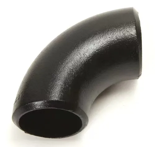
In the realm of engineering, particularly in piping design, the selection of fittings and their specifications is crucial for maintaining the efficiency and integrity of fluid transport systems. One such fitting that often garners attention is the elbow. An elbow is a pipe fitting that allows for a change in direction of the flow within a piping system. Among various types of elbows, the 1% 2% 90-degree elbow stands out due to its application in various industries and its significance in fluid flow dynamics.
What is a 90-Degree Elbow?
A 90-degree elbow is designed to connect two sections of pipe or tube while altering the flow direction by 90 degrees. This type of fitting is essential in configurations where space constraints require sharp turns, as opposed to gradual bends that might otherwise be utilized. The 1% 2% descriptor pertains to the specific design and performance characteristics associated with these elbows, particularly in relation to pressure loss and flow efficiency.
The Importance of 1% and 2% Designations
The numerical percentages often refer to the allowable pressure losses in a piping system when using specific fittings. In many engineering applications, maintaining optimal flow conditions is paramount, as excessive pressure drops can lead to inefficient system operation and increased energy consumption.
- 1% Loss A 1% loss designation implies that the fitting is engineered to allow only a minimal drop in pressure as the fluid navigates the change in direction. This is highly desirable in systems that require maximum efficiency and fluid velocity, such as in chemical processing or high-speed water transport systems.
- 2% Loss On the other hand, a 2% loss indicates a slightly higher tolerance for pressure drop. While still efficient, fittings designed with a 2% loss might be more suitable for less critical applications where minimizing pressure drop is not the primary concern. This could potentially be used in residential water supply lines or HVAC systems.
1 2 90 degree elbow

Flow Dynamics and Design Considerations
When selecting elbows for a piping system, one must consider the fluid's characteristics—such as viscosity and velocity—as well as the pipe diameter and material. The reduction in pressure resulting from these fittings is influenced by factors including the elbow's radius, length, and surface roughness. The 1% and 2% elbows are designed to optimize these parameters, striking a balance between manufacturability, cost, and performance.
In flow dynamics, the turbulent flow caused by sharp transitions can potentially lead to cavitation or erosion if the system isn’t designed properly. Effective fluid dynamics modeling must be employed to ensure that these elbows are utilized in a manner that minimizes energy loss while maximizing performance.
Applications in Industry
The application of 1% 2% 90-degree elbows spans various industries. In chemical manufacturing, these fittings contribute to the fluid transfer from reactors to storage tanks, maintaining the necessary pressure for optimal reactions. In HVAC systems, they facilitate efficient airflow, ensuring that heating and cooling systems operate within their ideal parameters. While in municipal water supply infrastructures, they allow for reliable transport across urban landscapes.
Conclusion
In summary, the 1% 2% 90-degree elbow is pivotal in fluid transport systems across numerous applications. Its design allows engineers to maintain efficiency while managing pressure losses that can impact system performance. As industries continue to evolve, the demand for efficient and effective piping solutions will ensure that the significance of such fittings remains paramount in engineering design practices. Effective selection and integration of these elbows in piping systems reflect the advancement in fluid dynamics understanding and engineering innovation.
Latest news
-
ANSI 150P SS304 SO FLANGE
NewsFeb.14,2025
-
ASTM A333GR6 STEEL PIPE
NewsJan.20,2025
-
ANSI B16.5 WELDING NECK FLANGE
NewsJan.15,2026
-
ANSI B16.5 SLIP-ON FLANGE
NewsApr.19,2024
-
SABS 1123 FLANGE
NewsJan.15,2025
-
DIN86044 PLATE FLANGE
NewsApr.19,2024
-
DIN2527 BLIND FLANGE
NewsApr.12,2024
-
JIS B2311 Butt-Welding Fittings LR/SR 45°/90° /180°Seamless/Weld
NewsApr.23,2024


