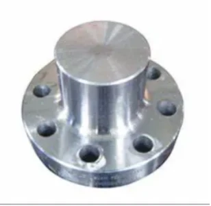
AWWA C207
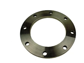
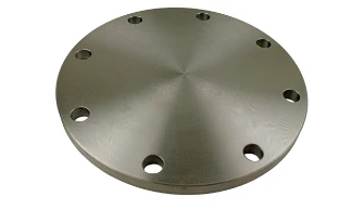
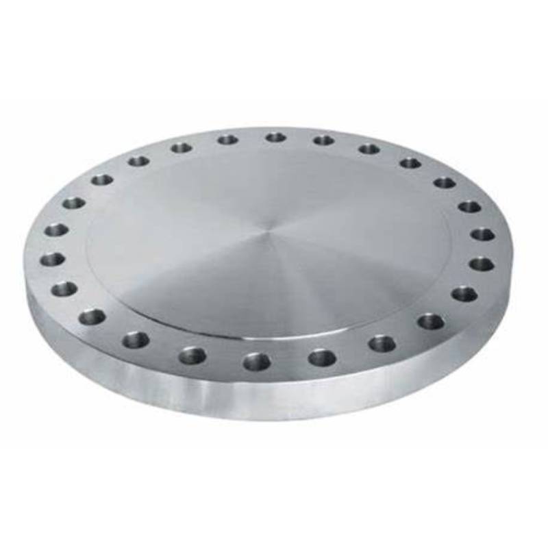
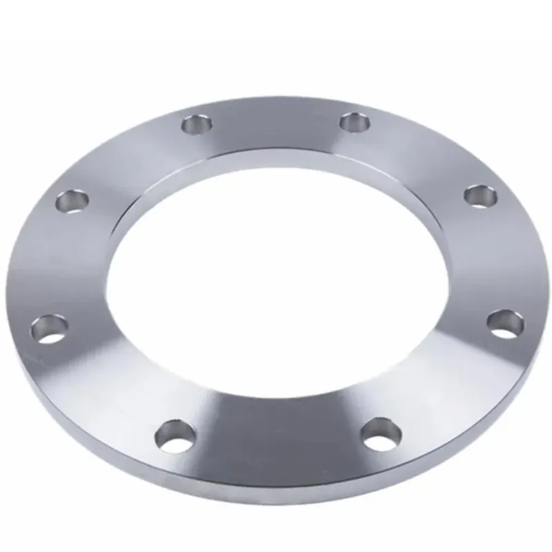
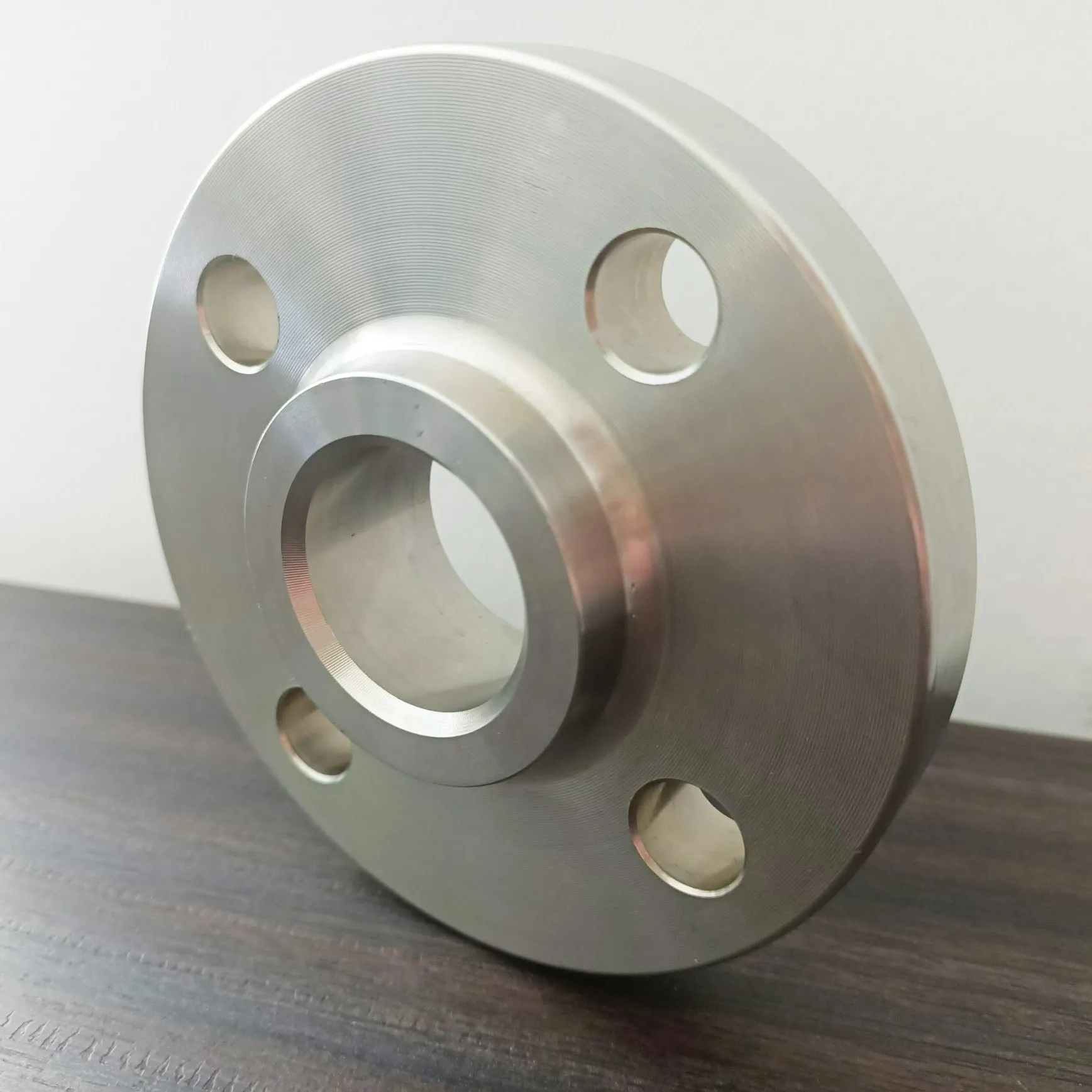
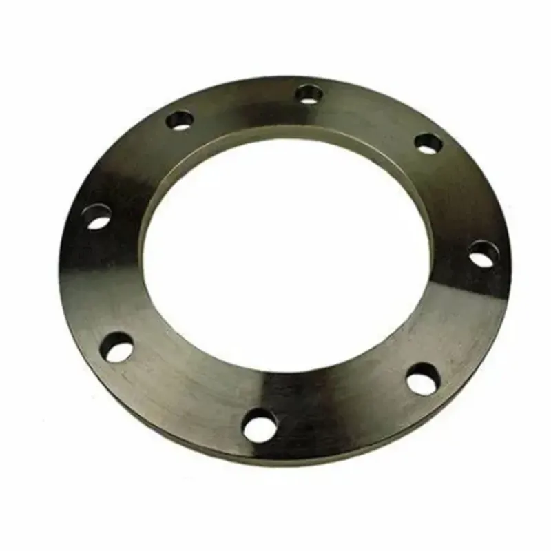
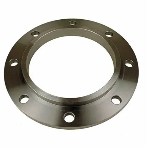
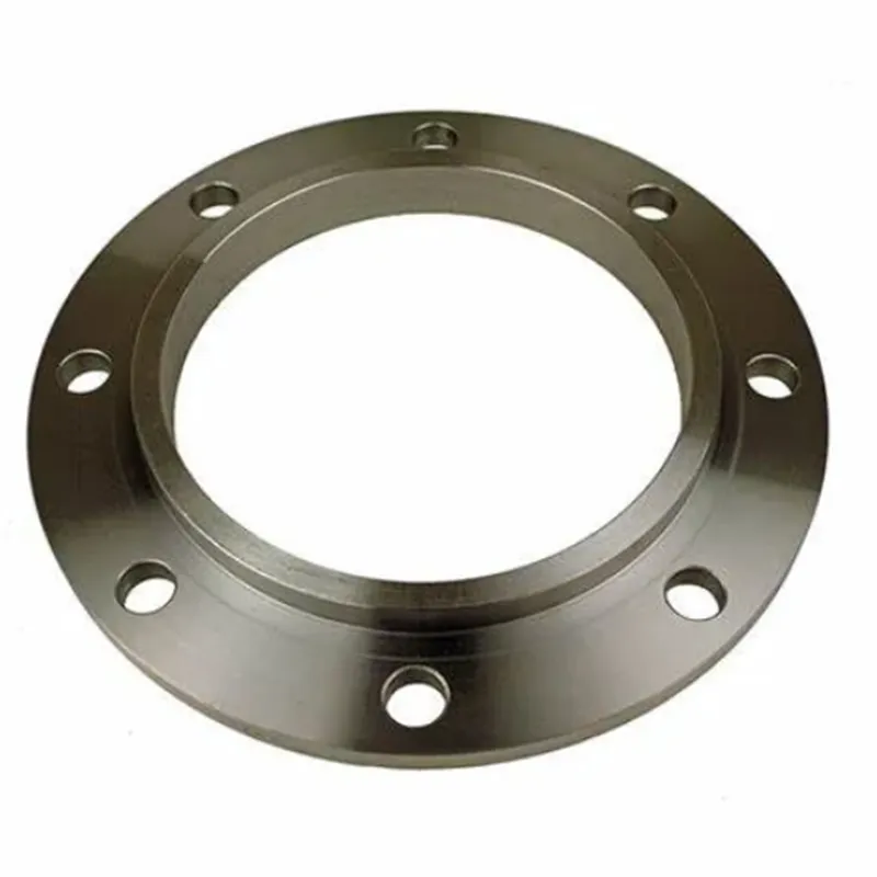
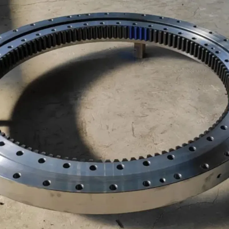
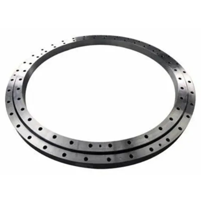
AWWA C207 flanges are designed according to the American Water Works Association (AWWA) standards, specifically for steel water pipe flanges used in municipal and industrial water systems. These common flange types ensure secure connections in low-pressure water service applications and are highly valued for their cost-effectiveness and durability, especially in large-diameter piping systems. AWWA C207 flanges are extensively used in water and wastewater treatment plants, irrigation systems, and municipal water supply networks. These flanges connect large-diameter pipes, valves, and pumps, ensuring efficient water transmission. Blind flanges in this standard are commonly used to close pipe ends for maintenance purposes, while ring and hub flanges facilitate efficient connections across long piping sections.
What is AWWA C207?
AWWA C207 is a standard developed by the American Water Works Association (AWWA) specifically for steel pipe flanges used in waterworks service. This standard, titled "AWWA C207: Steel Pipe Flanges for Waterworks Service—Sizes 4 In. Through 144 In. (100 mm Through 3,600 mm)," defines the dimensions, pressure classes, materials, and fabrication techniques for steel flanges commonly used in water transmission and distribution systems. The goal of AWWA C207 is to ensure that water infrastructure systems are safe, durable, and capable of withstanding the specific demands of water utility operations.
Key Features and Applications of AWWA C207
Flange Classes and Pressure Ratings
AWWA C207 specifies four primary flange classes: Class B, D, E, and F, each of which has distinct pressure ratings that suit various water pressure levels. For instance, Class B is designed for lower-pressure applications, while Class F can handle significantly higher pressures. This classification system allows water system engineers to select the appropriate flange for their specific pressure needs, ensuring system efficiency and safety.
2. Materials and Design
The AWWA C207 standard allows for flanges to be fabricated from carbon steel or stainless steel, ensuring durability and corrosion resistance in various water conditions. It also includes detailed guidelines on the dimensional requirements for bolt patterns, flange thickness, and gasket seats, providing compatibility with steel piping systems. Unlike some industrial flanges, AWWA C207 flanges are usually lighter and designed specifically for waterworks applications rather than high-pressure industrial uses.
3. Common Uses in Waterworks
AWWA C207 flanges are widely used in municipal water supply systems, wastewater treatment plants, and irrigation systems. These flanges ensure reliable, leak-proof connections between pipes, valves, and other equipment, allowing for efficient water distribution over long distances.
What is the Pressure Rating of AWWA C207?
The AWWA C207 standard is specifically designed for steel flanges used in waterworks piping systems, particularly for applications involving low-pressure water transmission. Unlike flanges used in high-pressure environments, AWWA C207 flanges are optimized for water infrastructure where pressures are relatively modest. The pressure ratings for AWWA C207 flanges vary by class, offering a range suitable for various pipeline needs in municipal and industrial water systems.
Pressure Ratings by Class With AWWA C207
AWWA C207 categorizes flanges into several classes (Class B, D, E, and F), each with distinct pressure ratings based on specific design and usage requirements:
Class B: These flanges are rated up to 86 psi and are typically used in applications that do not demand high pressure, such as certain municipal water systems or gravity-fed water pipelines.
Class D: Rated up to 175 psi, Class D flanges are the most commonly used in water systems where moderate pressure is required. These are suitable for most municipal and industrial waterworks projects, providing a reliable and economical option.
Class E: With a pressure rating of up to 275 psi, Class E flanges offer a higher capacity suitable for systems needing greater pressure support, often found in larger diameter piping or longer water transmission lines.
Class F: The highest rating under AWWA C207, Class F flanges can withstand pressures up to 300 psi, making them ideal for high-stress areas in waterworks systems where durability and strength are critical.
Applications and Considerations About AWWA C207
AWWA C207 flanges are tailored for water transmission rather than high-pressure industrial processes, focusing on the efficiency and cost-effectiveness required in municipal systems. This makes them ideal for use in water and wastewater treatment plants, irrigation systems, and large-scale municipal water supply lines, where their specific pressure ratings align well with low to moderate pressure requirements. The variety of classes offers engineers the flexibility to select the appropriate pressure rating for a safe, long-lasting water system.
AWWA C207 Flange Dimensions
AWWA C207 CLASS B
| Nominal Size |
Outside Diameter (OD) |
Sip-on Bore (ID) |
NO.of Bolt Holes |
Diameter Bot Holes |
Bot Cirdle (BC) |
Thickness(T) | Weight Each | ||
| CLA | SS B | ||||||||
| Sip-on | Bind | Sip-on | Blind | ||||||
| 4 | 228.6 | 116.1 | 8 | 19.1 | 190.5 | 15.9 | 15.9 | 3.52 | 4.84 |
| 5 | 254 | 143.8 | 8 | 22.2 | 215.9 | 15.9 | 15.9 | 3.91 | 5.94 |
| 6 | 279.4 | 170.7 | 8 | 22.2 | 241.3 | 17.5 | 17.5 | 4.86 | 8 |
| 8 | 342.9 | 221.5 | 8 | 22.2 | 298.5 | 17.5 | 17.5 | 6.97 | 12.27 |
| 10 | 406.4 | 276.4 | 12 | 25.4 | 362 | 17.5 | 17.5 | 8.75 | 17 |
| 12 | 482.6 | 327.2 | 12 | 25.4 | 431.8 | 17.5 | 18.3 | 12.75 | 25.42 |
| 14 | 533.4 | 360.4 | 12 | 28.6 | 476.3 | 17.5 | 20.1 | 15.64 | 34.07 |
| 16 | 596.9 | 411.2 | 16 | 28.6 | 539.8 | 17.5 | 22.7 | 18.8 | 48.07 |
| 18 | 635 | 462 | 16 | 31.8 | 577.9 | 17.5 | 24.1 | 18.74 | 57.55 |
| 20 | 698.5 | 512.8 | 20 | 31.8 | 635 | 17.5 | 26.4 | 22.1 | 76.18 |
| 22 | 749.3 | 563.6 | 20 | 34.9 | 692.2 | 19.1 | 28.8 | 25.86 | 95.44 |
| 24 | 812.8 | 614.4 | 20 | 34.9 | 749.3 | 19.1 | 30.9 | 30.5 | 121.31 |
| 26 | 869.95 | 666.8 | 24 | 34.9 | 806.5 | 20.6 | 33.2 | 35.96 | 149.04 |
| 28 | 927.1 | 717.6 | 28 | 34.9 | 863.3 | 22.2 | 35.5 | 42.52 | 180.79 |
| 30 | 984.25 | 768.4 | 28 | 34.9 | 914.4 | 22.2 | 37.5 | 47.15 | 216.25 |
| 32 | 1060.5 | 819.2 | 28 | 41.3 | 977.9 | 23.8 | 40.2 | 59.59 | 267.11 |
| 34 | 1111.3 | 870 | 32 | 41.3 | 1028.7 | 23.8 | 42.2 | 62.19 | 307.35 |
| 36 | 1168.4 | 920.8 | 32 | 41.3 | 1085.9 | 25.4 | 44.5 | 72.51 | 359.84 |
| 38 | 1238.3 | 971.6 | 32 | 41.3 | 1149.4 | 25.4 | 47.1 | 83.81 | 429.75 |
| 40 | 1289.1 | 1022.4 | 36 | 41.3 | 1200.2 | 25.4 | 49.1 | 86.99 | 484.83 |
| 42 | 1346.2 | 1073.2 | 36 | 41.3 | 1257.3 | 28.6 | 51.4 | 105.72 | 555.26 |
| 44 | 1403.4 | 1124 | 40 | 41.3 | 1314.5 | 28.6 | 53.7 | 112.57 | 629.96 |
| 48 | 1511.3 | 1225.6 | 44 | 41.3 | 1422.4 | 31.8 | 58 | 138.69 | 790.5 |
| 54 | 1682.8 | 1378 | 44 | 47.6 | 1593.9 | 34.9 | 65 | 179.42 | 1095.72 |
| 60 | 1854.2 | 1530.4 | 52 | 47.6 | 1759 | 38.1 | 71.6 | 229.93 | 1466.79 |
| 66 | 2032 | 1682.8 | 52 | 47.6 | 1930.4 | 41.3 | 78.5 | 300.53 | 1942.81 |
| 72 | 2197.1 | 1835.2 | 60 | 47.6 | 2095.5 | 44.5 | 85.2 | 363.34 | 2466.14 |
| 78 | 2362.2 | 1987.6 | 64 | 54 | 2260.6 | 50.8 | 452.23 | ||
| 84 | 2533.7 | 2140 | 64 | 54 | 2425.7 | 50.8 | 518.24 | ||
| 90 | 2705.1 | 2292.4 | 68 | 61.9 | 2590.8 | 57.2 | 635.94 | ||
| 96 | 2876.6 | 2444.8 | 68 | 61.9 | 2755.9 | 57.2 | 718.99 | ||
| 102 | 3048 | 2597.2 | 72 | 68.3 | 2908.3 | 63.5 | 865.47 | ||
| 108 | 3219.5 | 2749.6 | 72 | 68.3 | 3067.1 | 63.5 | 967.34 | ||
| 120 | 3562.4 | 3054.4 | 76 | 74.6 | 3371.9 | 69.9 | 1267.3 | ||
| 132 | 3905.3 | 3359.2 | 80 | 81 | 3702.1 | 76.2 | 1618.4 | ||
| 144 | 4248.2 | 3664 | 84 | 87.3 | 4019.6 | 82.6 | 2029.5 | ||
AWWA C207 CLASS D
| Nominal Size |
Outside Diameter (OD) |
Sip-on Bore (ID) |
NO.of Bott Holes |
Diameter Bolt Holes |
Bot Circle (BC) |
Thickness(T) | Weight Each | ||
| CLA | SSD | ||||||||
| Slip-on | Blind | Sip-on | Blnd | ||||||
| 4 | 228.6 | 116.1 | 8 | 19.1 | 190.5 | 15.9 | 15.9 | 3.52 | 4.84 |
| 5 | 254 | 143.8 | 8 | 22.2 | 215.9 | 15.9 | 16.5 | 3.91 | 6.17 |
| 6 | 279.4 | 170.7 | 8 | 22.2 | 241.3 | 17.5 | 17.6 | 4.86 | 8.05 |
| 8 | 342.9 | 221.5 | 8 | 22.2 | 298.5 | 17.5 | 20.6 | 6.97 | 14.44 |
| 10 | 406.4 | 276.4 | 12 | 25.4 | 362 | 17.5 | 24.2 | 8.75 | 23.5 |
| 12 | 482.6 | 327.2 | 12 | 25.4 | 431.8 | 20.6 | 28.4 | 15.01 | 39.45 |
| 14 | 533.4 | 360.4 | 12 | 28.6 | 476.3 | 23.8 | 28.8 | 21.27 | 48.81 |
| 16 | 596.9 | 411.2 | 16 | 28.6 | 539.8 | 25.4 | 32.1 | 27.29 | 67.97 |
| 18 | 635 | 462 | 16 | 31.8 | 577.9 | 27 | 33.8 | 28.92 | 80.72 |
| 20 | 698.5 | 512.8 | 20 | 31.8 | 635 | 28.6 | 36.8 | 36.12 | 106.19 |
| 22 | 749.3 | 563.6 | 20 | 34.9 | 692.2 | 30.2 | 39.8 | 40.89 | 131.89 |
| 24 | 812.8 | 614.4 | 20 | 34.9 | 749.3 | 31.8 | 42.2 | 50.78 | 165.67 |
| 26 | 869.95 | 666.8 | 24 | 34.9 | 806.5 | 33.3 | 45.4 | 58.14 | 203.81 |
| 28 | 927.1 | 717.6 | 28 | 34.9 | 863.3 | 33.3 | 48.4 | 63.79 | 246.49 |
| 30 | 984.25 | 768.4 | 28 | 34.9 | 914.4 | 34.9 | 51 | 74.12 | 294.1 |
| 32 | 1060.5 | 819.2 | 28 | 41.3 | 977.9 | 38.1 | 54.6 | 95.4 | 362.79 |
| 34 | 1111.3 | 870 | 32 | 41.3 | 1028.7 | 38.1 | 57.2 | 99.56 | 416.59 |
| 36 | 1168.4 | 920.8 | 32 | 41.3 | 1085.9 | 41.3 | 60.2 | 117.91 | 486.79 |
| 38 | 1238.3 | 971.6 | 32 | 41.3 | 1149.4 | 41.3 | 63.7 | 136.28 | 581.21 |
| 40 | 1289.1 | 1022.4 | 36 | 41.3 | 1200.2 | 41.3 | 66.3 | 141.44 | 654.67 |
| 42 | 1346.2 | 1073.2 | 36 | 41.3 | 1257.3 | 44.5 | 69.3 | 164.49 | 748.63 |
| 44 | 1403.4 | 1124 | 40 | 41.3 | 1314.5 | 44.5 | 72.4 | 175.15 | 849.33 |
| 48 | 1511.3 | 1225.6 | 44 | 41.3 | 1422.4 | 47.6 | 78 | 207.61 | 1063.09 |
| 54 | 1682.8 | 1378 | 44 | 47.6 | 1593.9 | 54 | 87.2 | 277.62 | 1469.95 |
| 60 | 1854.2 | 1530.4 | 52 | 47.6 | 1759 | 57.2 | 96 | 345.2 | 1966.64 |
| 66 | 2032 | 1682.8 | 52 | 47.6 | 1930.4 | 63.5 | 105 | 462.08 | 2598.66 |
| 72 | 2197.1 | 1835.2 | 60 | 47.6 | 2095.5 | 66.7 | 114 | 544.61 | 3299.77 |
| 78 | 2362.2 | 1987.6 | 64 | 54 | 2260.6 | 69.9 | 622.26 | ||
| 84 | 2533.7 | 2140 | 64 | 54 | 2425.7 | 73 | 744.71 | ||
| 90 | 2705.1 | 2292.4 | 68 | 61.9 | 2590.8 | 76.2 | 847.18 | ||
| 96 | 2876.6 | 2444.8 | 68 | 61.9 | 2755.9 | 82.6 | 1038.26 | ||
| 102 | 3048 | 2597.2 | 72 | 68.3 | 2908.3 | 82.6 | 1125.79 | ||
| 108 | 3219.5 | 2749.6 | 72 | 68.3 | 3067.1 | 85.7 | 1305.53 | ||
| 120 | 3562.4 | 3054.4 | 76 | 74.6 | 3371.9 | 88.9 | 1611.74 | ||
| 132 | 3905.3 | 3359.2 | 80 | 81 | 3702.1 | 98.4 | 2089.89 | ||
| 144 | 4248.2 | 3664 | 84 | 87.3 | 4019.6 | 105 | 2579.82 | ||
AWWA C207-07-Ring&Blinds. CLASS B
| Nominal Size |
Outside Diameter (OD) |
Sip-on Bore (ID) |
NO.of Bolt Holes |
Diameter Bot Holes |
Bot Cirdle (BC) |
Thickness(T) | Weight Each | ||
| CLA | SS B | ||||||||
| Sip-on | Bind | Sip-on | Blind | ||||||
| 4 | 228.6 | 116.1 | 8 | 19.1 | 190.5 | 15.9 | 15.9 | 3.52 | 4.84 |
| 5 | 254 | 143.8 | 8 | 22.2 | 215.9 | 15.9 | 15.9 | 3.91 | 5.94 |
| 6 | 279.4 | 170.7 | 8 | 22.2 | 241.3 | 17.5 | 17.5 | 4.86 | 8 |
| 8 | 342.9 | 221.5 | 8 | 22.2 | 298.5 | 17.5 | 17.5 | 6.97 | 12.27 |
| 10 | 406.4 | 276.4 | 12 | 25.4 | 362 | 17.5 | 17.5 | 8.75 | 17 |
| 12 | 482.6 | 327.2 | 12 | 25.4 | 431.8 | 17.5 | 18.3 | 12.75 | 25.42 |
| 14 | 533.4 | 360.4 | 12 | 28.6 | 476.3 | 17.5 | 20.1 | 15.64 | 34.07 |
| 16 | 596.9 | 411.2 | 16 | 28.6 | 539.8 | 17.5 | 22.7 | 18.8 | 48.07 |
| 18 | 635 | 462 | 16 | 31.8 | 577.9 | 17.5 | 24.1 | 18.74 | 57.55 |
| 20 | 698.5 | 512.8 | 20 | 31.8 | 635 | 17.5 | 26.4 | 22.1 | 76.18 |
| 22 | 749.3 | 563.6 | 20 | 34.9 | 692.2 | 19.1 | 28.8 | 25.86 | 95.44 |
| 24 | 812.8 | 614.4 | 20 | 34.9 | 749.3 | 19.1 | 30.9 | 30.5 | 121.31 |
| 26 | 869.95 | 666.8 | 24 | 34.9 | 806.5 | 20.6 | 33.2 | 35.96 | 149.04 |
| 28 | 927.1 | 717.6 | 28 | 34.9 | 863.3 | 22.2 | 35.5 | 42.52 | 180.79 |
| 30 | 984.25 | 768.4 | 28 | 34.9 | 914.4 | 22.2 | 37.5 | 47.15 | 216.25 |
| 32 | 1060.5 | 819.2 | 28 | 41.3 | 977.9 | 23.8 | 40.2 | 59.59 | 267.11 |
| 34 | 1111.3 | 870 | 32 | 41.3 | 1028.7 | 23.8 | 42.2 | 62.19 | 307.35 |
| 36 | 1168.4 | 920.8 | 32 | 41.3 | 1085.9 | 25.4 | 44.5 | 72.51 | 359.84 |
| 38 | 1238.3 | 971.6 | 32 | 41.3 | 1149.4 | 25.4 | 47.1 | 83.81 | 429.75 |
| 40 | 1289.1 | 1022.4 | 36 | 41.3 | 1200.2 | 25.4 | 49.1 | 86.99 | 484.83 |
| 42 | 1346.2 | 1073.2 | 36 | 41.3 | 1257.3 | 28.6 | 51.4 | 105.72 | 555.26 |
| 44 | 1403.4 | 1124 | 40 | 41.3 | 1314.5 | 28.6 | 53.7 | 112.57 | 629.96 |
| 48 | 1511.3 | 1225.6 | 44 | 41.3 | 1422.4 | 31.8 | 58 | 138.69 | 790.5 |
| 54 | 1682.8 | 1378 | 44 | 47.6 | 1593.9 | 34.9 | 65 | 179.42 | 1095.72 |
| 60 | 1854.2 | 1530.4 | 52 | 47.6 | 1759 | 38.1 | 71.6 | 229.93 | 1466.79 |
| 66 | 2032 | 1682.8 | 52 | 47.6 | 1930.4 | 41.3 | 78.5 | 300.53 | 1942.81 |
| 72 | 2197.1 | 1835.2 | 60 | 47.6 | 2095.5 | 44.5 | 85.2 | 363.34 | 2466.14 |
| 78 | 2362.2 | 1987.6 | 64 | 54 | 2260.6 | 50.8 | 452.23 | ||
| 84 | 2533.7 | 2140 | 64 | 54 | 2425.7 | 50.8 | 518.24 | ||
| 90 | 2705.1 | 2292.4 | 68 | 61.9 | 2590.8 | 57.2 | 635.94 | ||
| 96 | 2876.6 | 2444.8 | 68 | 61.9 | 2755.9 | 57.2 | 718.99 | ||
| 102 | 3048 | 2597.2 | 72 | 68.3 | 2908.3 | 63.5 | 865.47 | ||
| 108 | 3219.5 | 2749.6 | 72 | 68.3 | 3067.1 | 63.5 | 967.34 | ||
| 120 | 3562.4 | 3054.4 | 76 | 74.6 | 3371.9 | 69.9 | 1267.3 | ||
| 132 | 3905.3 | 3359.2 | 80 | 81 | 3702.1 | 76.2 | 1618.4 | ||
| 144 | 4248.2 | 3664 | 84 | 87.3 | 4019.6 | 82.6 | 2029.5 | ||
AWWA C207-07-Ring&Blinds. CLASS D
| Nominal Sze |
Outside Diameter (OD) |
Sip-on Bore (ID) |
NO.of Bott Holes |
Diameter Bolt Holes |
Bot Circle (BC) |
Thickness(T) | Weight Each | ||
| CLA | SSD | ||||||||
| Slip-on | Blind | Sip-on | Blnd | ||||||
| 4 | 228.6 | 116.1 | 8 | 19.1 | 190.5 | 15.9 | 15.9 | 3.52 | 4.84 |
| 5 | 254 | 143.8 | 8 | 22.2 | 215.9 | 15.9 | 16.5 | 3.91 | 6.17 |
| 6 | 279.4 | 170.7 | 8 | 22.2 | 241.3 | 17.5 | 17.6 | 4.86 | 8.05 |
| 8 | 342.9 | 221.5 | 8 | 22.2 | 298.5 | 17.5 | 20.6 | 6.97 | 14.44 |
| 10 | 406.4 | 276.4 | 12 | 25.4 | 362 | 17.5 | 24.2 | 8.75 | 23.5 |
| 12 | 482.6 | 327.2 | 12 | 25.4 | 431.8 | 20.6 | 28.4 | 15.01 | 39.45 |
| 14 | 533.4 | 360.4 | 12 | 28.6 | 476.3 | 23.8 | 28.8 | 21.27 | 48.81 |
| 16 | 596.9 | 411.2 | 16 | 28.6 | 539.8 | 25.4 | 32.1 | 27.29 | 67.97 |
| 18 | 635 | 462 | 16 | 31.8 | 577.9 | 27 | 33.8 | 28.92 | 80.72 |
| 20 | 698.5 | 512.8 | 20 | 31.8 | 635 | 28.6 | 36.8 | 36.12 | 106.19 |
| 22 | 749.3 | 563.6 | 20 | 34.9 | 692.2 | 30.2 | 39.8 | 40.89 | 131.89 |
| 24 | 812.8 | 614.4 | 20 | 34.9 | 749.3 | 31.8 | 42.2 | 50.78 | 165.67 |
| 26 | 869.95 | 666.8 | 24 | 34.9 | 806.5 | 33.3 | 45.4 | 58.14 | 203.81 |
| 28 | 927.1 | 717.6 | 28 | 34.9 | 863.3 | 33.3 | 48.4 | 63.79 | 246.49 |
| 30 | 984.25 | 768.4 | 28 | 34.9 | 914.4 | 34.9 | 51 | 74.12 | 294.1 |
| 32 | 1060.5 | 819.2 | 28 | 41.3 | 977.9 | 38.1 | 54.6 | 95.4 | 362.79 |
| 34 | 1111.3 | 870 | 32 | 41.3 | 1028.7 | 38.1 | 57.2 | 99.56 | 416.59 |
| 36 | 1168.4 | 920.8 | 32 | 41.3 | 1085.9 | 41.3 | 60.2 | 117.91 | 486.79 |
| 38 | 1238.3 | 971.6 | 32 | 41.3 | 1149.4 | 41.3 | 63.7 | 136.28 | 581.21 |
| 40 | 1289.1 | 1022.4 | 36 | 41.3 | 1200.2 | 41.3 | 66.3 | 141.44 | 654.67 |
| 42 | 1346.2 | 1073.2 | 36 | 41.3 | 1257.3 | 44.5 | 69.3 | 164.49 | 748.63 |
| 44 | 1403.4 | 1124 | 40 | 41.3 | 1314.5 | 44.5 | 72.4 | 175.15 | 849.33 |
| 48 | 1511.3 | 1225.6 | 44 | 41.3 | 1422.4 | 47.6 | 78 | 207.61 | 1063.09 |
| 54 | 1682.8 | 1378 | 44 | 47.6 | 1593.9 | 54 | 87.2 | 277.62 | 1469.95 |
| 60 | 1854.2 | 1530.4 | 52 | 47.6 | 1759 | 57.2 | 96 | 345.2 | 1966.64 |
| 66 | 2032 | 1682.8 | 52 | 47.6 | 1930.4 | 63.5 | 105 | 462.08 | 2598.66 |
| 72 | 2197.1 | 1835.2 | 60 | 47.6 | 2095.5 | 66.7 | 114 | 544.61 | 3299.77 |
| 78 | 2362.2 | 1987.6 | 64 | 54 | 2260.6 | 69.9 | 622.26 | ||
| 84 | 2533.7 | 2140 | 64 | 54 | 2425.7 | 73 | 744.71 | ||
| 90 | 2705.1 | 2292.4 | 68 | 61.9 | 2590.8 | 76.2 | 847.18 | ||
| 96 | 2876.6 | 2444.8 | 68 | 61.9 | 2755.9 | 82.6 | 1038.26 | ||
| 102 | 3048 | 2597.2 | 72 | 68.3 | 2908.3 | 82.6 | 1125.79 | ||
| 108 | 3219.5 | 2749.6 | 72 | 68.3 | 3067.1 | 85.7 | 1305.53 | ||
| 120 | 3562.4 | 3054.4 | 76 | 74.6 | 3371.9 | 88.9 | 1611.74 | ||
| 132 | 3905.3 | 3359.2 | 80 | 81 | 3702.1 | 98.4 | 2089.89 | ||
| 144 | 4248.2 | 3664 | 84 | 87.3 | 4019.6 | 105 | 2579.82 | ||
