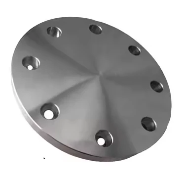
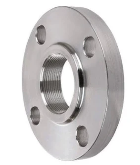
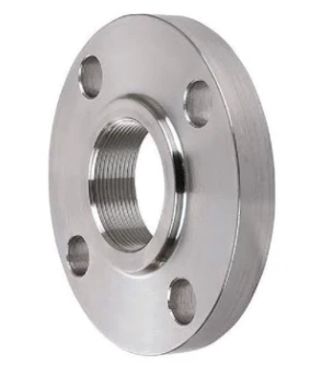
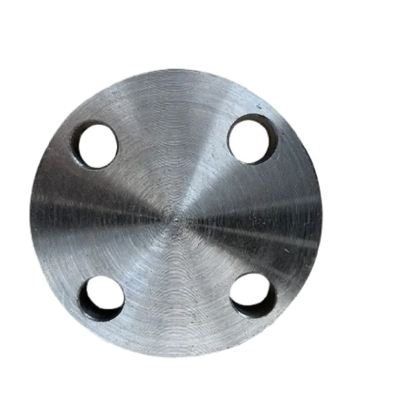
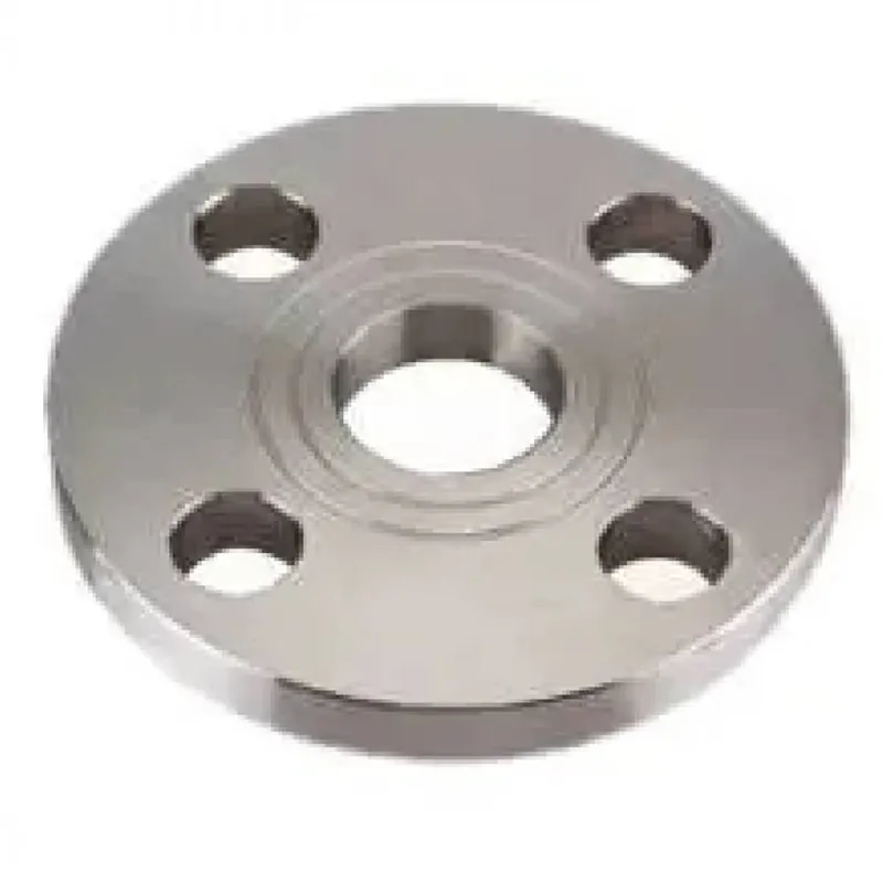
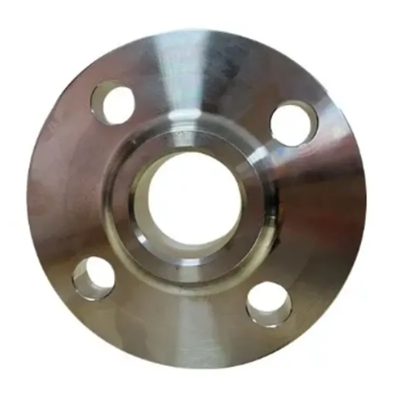
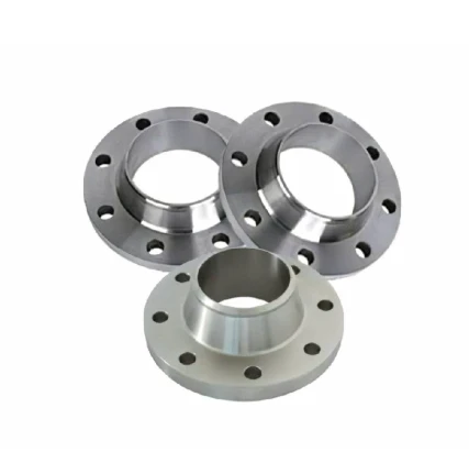
JIS B2220 FLANGE
The JIS B 2220 flange offers several advantages that make it a preferred choice in various industrial applications. Designed according to Japanese Industrial Standards (JIS), this flange is renowned for its high quality, precision engineering, and durability. One of the key benefits of the JIS B 2220 flange is its ability to provide a reliable, secure connection in piping systems, ensuring minimal leakage and enhanced safety. The flange is available in multiple pressure ratings, including 5K, 10K, and 20K, allowing flexibility for use in different pressure environments. Its wide range of sizes and configurations further adds to its versatility, making it suitable for various industries, from oil and gas to chemical processing and water treatment.
Another advantage of the JIS B 2220 flange is its ease of installation and maintenance. The standardized dimensions ensure compatibility with other piping components, reducing installation time and effort. Additionally, its robust design minimizes the risk of wear and tear, meaning fewer replacements and lower maintenance costs over time. Flanges made to JIS B 2220 specifications are often constructed from high-grade materials such as carbon steel, stainless steel, and alloy steel, providing excellent resistance to corrosion and high temperatures, and making them suitable for use in harsh environments.
Furthermore, the precise dimensions of the JIS B 2220 flange—including options like JIS B 2220 10K flange dimensions and JIS B 2220 5K flange dimensions—allow for tight, secure seals, ensuring the integrity of the piping system. This level of reliability is crucial in industries where maintaining fluid containment is critical. Overall, the JIS B 2220 flange combines reliability, durability, and flexibility, making it a dependable choice for a wide range of applications.
What Is JIS Standard for Flanges?
In industrial applications, the choice of common flange types is critical for ensuring the integrity and safety of piping systems. One prominent standard that governs the specifications for flanges in Japan is the JIS standard, specifically the JIS B 2220 flange. Established by the Japanese Industrial Standards (JIS), this standard outlines the dimensions, materials, and testing requirements for flanges used in various applications, including water and gas pipelines, chemical processing, and manufacturing.
The JIS B 2220 flange is designed to provide reliable connections in piping systems through a series of detailed specifications. It encompasses various types of flanges, including welding neck, slip-on, blind, and threaded options. These flanges are available in different sizes, pressure ratings, and materials, enabling engineers to select the appropriate flange that meets their project requirements.
One of the key advantages of using JIS B 2220 flanges is their compatibility with international standards. This makes it easier for engineers and procurement specialists to source flanges that can seamlessly integrate into existing piping systems, particularly in projects that involve collaboration between Japanese and international stakeholders. Furthermore, adherence to the JIS standard ensures that flanges maintain high quality, durability, and resistance to corrosion.
In conclusion, understanding the requirements of the JIS B 2220 flange is vital for anyone involved in the design or maintenance of piping systems. This standard not only facilitates interoperability but also promotes the overall efficiency and safety of industrial operations. As industries continue to evolve, the demand for reliable and high-quality components like JIS B 2220 flanges will remain steadfast, underscoring the importance of adhering to recognized standards. For engineers and project managers, making informed decisions about flange specifications can lead to enhanced system performance and longevity.
What Is the Difference Between JIS and ANSI Flange?
What are JIS and ANSI Flanges?
JIS Flanges refer to the standards established by the Japanese Industrial Standard (JIS). The JIS B 2220 flange specification defines the dimensions, tolerances, and pressure ratings for flanges used in various industrial applications. JIS flanges are commonly found in Japanese manufacturing and are typically manufactured to metric dimensions.
ANSI Flanges, on the other hand, pertains to the standards set by the American National Standards Institute (ANSI). ANSI flanges often follow the American Society of Mechanical Engineers (ASME) standards, primarily ASME B16.5 for pipe flanges, which utilize inch-based measurements. ANSI flanges are prevalent in the United States and other countries that adopt these standards.
Key Differences Between JIS and ANSI Flanges
1. Measurement System:
One of the most significant differences between JIS and ANSI flanges is the measurement system used. JIS flanges utilize the metric system—typically expressed in millimeters—while ANSI flanges are based on the imperial system—expressed in inches.
2. Design and Pressure Ratings:
Flanges come in various pressure ratings, and JIS B 2220 flanges are categorized into different classes based on their pressure-handling capabilities. For example, categories such as 5K, 10K, and 16K indicate the different levels of pressure tolerance. In contrast, ANSI flanges are classified by ANSI classes, where common classes are 150, 300, 600, 900, 1500, and 2500, indicating their pressure ratings.
3. Application and Use:
The choice between JIS and ANSI flanges often depends on regional practices and specific application requirements. JIS B 2220 flanges are primarily used in Japan and are suitable for industries like energy, chemical processing, and water treatment. ANSI flanges are more common in North America and are widely used in similar sectors.
4. Bolt Patterns and Dimensions:
The bolt patterns and overall dimensions of JIS and ANSI flanges differ. JIS B 2220 flanges have specific bolt circle diameters, numbers of bolt holes, and hole diameters unique to the JIS standard, whereas ANSI flanges follow their own set of dimensions, which can lead to compatibility issues between the two if not properly matched.
JIS B 2220 Flange FAQs
Q1: What is the JIS B 2220 flange used for?
A1: The JIS B 2220 flange is widely used in various industrial applications to connect pipes, valves, pumps, and other equipment in a piping system. It is designed to provide a reliable and robust joint that can withstand high pressure and temperature conditions, ensuring the integrity of your piping system. Whether you’re in the oil, gas, chemical, or water treatment industry, this flange is an excellent choice for ensuring safe and efficient operations.
Q2: What materials are available for JIS B 2220 flanges?
A2: JIS B 2220 flanges are available in a variety of materials to suit different operating environments and requirements. Common materials include carbon steel, stainless steel, and alloy steel. Each material offers unique benefits, such as corrosion resistance and strength. When selecting a flange, consider the specific application and operating conditions to ensure you choose the right material for optimal performance.
Q3: Are JIS B 2220 flanges compatible with ISO or ANSI flanges?
A3: While the JIS B 2220 flange is a standard that follows Japanese Industrial Standards, it features compatibility aspects with certain ISO and ANSI flanges. However, it's crucial to verify the dimensions, pressure ratings, and bolt-hole patterns to ensure an appropriate fit. We recommend consulting with your engineering team or a flange specialist to confirm compatibility for your specific application.
Q4: How do I ensure proper installation of the JIS B 2220 flange?
A4: To ensure proper installation of the JIS B 2220 flange, begin by cleaning the flange surfaces to remove any dirt or debris. Use a suitable gasket material that complies with your specific application requirements and is rated for pressure and temperature. Align the flanges correctly and insert bolts uniformly to avoid uneven stress distribution. It’s vital to tighten the bolts to the recommended torque specifications to ensure a secure and leak-free connection.
Q5: What are the pressure ratings for JIS B 2220 flanges?
A5: JIS B 2220 flanges feature various pressure ratings, typically ranging from 5K to 20K pressure classes. The exact rating depends on both the flange size and the material used. When selecting the appropriate flange, always reference the manufacturer's specifications to ensure it meets the requirements of your specific application, as using a flange with an inadequate pressure rating can lead to failures or leaks.
Q6: Can I order custom sizes of JIS B 2220 flanges?
A6: We offer the option to order custom sizes of JIS B 2220 flanges to meet your specific engineering needs. Customization may include different diameters, thicknesses, or material grades. To place a custom order, please contact our customer service team with your specific requirements, and we’ll assist you in finding the right solution for your project.
JIS B2220 Flange Dimensions
| 1K KS V 7815 JIS F 7805 SLIP-ON FLANGES Unit:mm |
|||||||||
| N/D | TUDIA | BRIDA | BOLT HOLE | BOLT (M) |
WT (KG) |
||||
| O/D(d) | D | I/D(do) | T | C | N | H | |||
| 25 | 34.0 | 95 | 34.5 | 10 | 75 | 4 | 12 | M10 | 0.45 |
| (32) | 42.7 | 115 | 432 | 12 | 90 | 4 | 15 | M12 | 0.73 |
| 40 | 48.6 | 120 | 49.1 | 12 | 95 | 4 | 15 | M12 | 0.83 |
| 50 | 60.5 | 130 | 61.1 | 14 | 105 | 4 | 15 | M12 | 1.06 |
| 65 | 76.3 | 155 | 77.1 | 14 | 130 | 4 | 15 | M12 | 1.48 |
| 80 | 89.1 | 180 | 90.0 | 14 | 145 | 4 | 19 | M16 | 1.97 |
| 100 | 114.3 | 200 | 115.4 | 16 | 165 | 8 | 19 | M16 | 2.35 |
| 125 | 139.8 | 235 | 141.2 | 16 | 200 | 8 | 19 | M16 | 3.20 |
| 150 | 165.2 | 265 | 166.6 | 16 | 230 | 8 | 19 | M16 | 3.90 |
| 200 | 216.3 | 320 | 218.0 | 16 | 280 | 8 | 23 | M20 | 5.00 |
| 250 | 267.4 | 385 | 269.5 | 16 | 345 | 12 | 23 | M20 | 6.83 |
| 300 | 318.5 | 430 | 321.0 | 16 | 390 | 12 | 23 | M20 | 7.45 |
| 350 | 355.6 | 480 | 358.1 | 16 | 435 | 12 | 25 | M22 | 9.45 |
| 400 | 406.4 | 540 | 409.0 | 16 | 495 | 16 | 25 | M22 | 11.43 |
| 450 | 457.2 | 605 | 460.0 | 16 | 555 | 16 | 25 | M22 | 14.40 |
| 500 | 508.0 | 655 | 511.0 | 16 | 605 | 16 | 25 | M22 | 15.73 |
| (550) | 555.8 | 660 | 562.0 | 16 | 620 | 16 | 23 | M20 | 12.00 |
| 600 | 609.6 | 710 | 613.0 | 16 | 670 | 16 | 23 | M20 | 12.12 |
| (650) | 660.4 | 760 | 664.0 | 16 | 720 | 16 | 23 | M20 | 12.15 |
| 700 | 711.2 | 815 | 715.0 | 16 | 775 | 16 | 23 | M20 | 14.26 |
| 750 | 762.0 | 865 | 766.0 | 16 | 825 | 20 | 23 | M20 | 14.88 |
| 800 | 812.8 | 915 | 817.0 | 16 | 875 | 20 | 23 | M20 | 15.70 |
| (850) | 863.6 | 965 | 868.0 | 16 | 925 | 20 | 23 | M20 | 16.50 |
| 900 | 914.4 | 1025 | 919.0 | 18 | 980 | 20 | 25 | M22 | 21.48 |
| (950) | 962.0 | 1075 | 967.0 | 18 | 1030 | 20 | 25 | M22 | 21.97 |
| 1000 | 1016.0 | 1125 | 1021.0 | 18 | 1080 | 20 | 25 | M22 | 23.38 |
| 1050 | 1062.0 | 1175 | 1067.0 | 18 | 1130 | 24 | 25 | M22 | 25.21 |
| 1100 | 1117.6 | 1225 | 1122.0 | 18 | 1180 | 24 | 25 | M22 | 25.16 |
| 1150 | 1162.0 | 1275 | 1167.0 | 18 | 1230 | 24 | 25 | M22 | 26.64 |
| 1200 | 1219.0 | 1325 | 1224.0 | 18 | 1280 | 24 | 25 | M22 | 27.60 |
| 1250 | 1262.0 | 1375 | 1267.0 | 18 | 1330 | 28 | 25 | M22 | 29.72 |
| 1300 | 1312.0 | 1425 | 1317.0 | 18 | 1380 | 28 | 25 | M22 | 30.92 |
| 1350 | 1371.6 | 1475 | 1376.0 | 18 | 1430 | 28 | 25 | M22 | 32.38 |
| 1400 | 1412.0 | 1525 | 1417.0 | 20 | 1480 | 28 | 25 | M22 | 37.02 |
| 1450 | 1462.0 | 1595 | 1467.0 | 20 | 1540 | 28 | 27 | M24 | 45.81 |
| 1500 | 1524.0 | 1645 | 1529.0 | 20 | 1590 | 28 | 27 | M24 | 46.88 |
| 1600 | 1612.0 | 1745 | 1617.0 | 20 | 1690 | 28 | 27 | M24 | 50.54 |
| 1700 | 1712.0 | 1845 | 1717.0 | 20 | 1790 | 28 | 27 | M24 | 53.70 |
| 1800 | 1812.0 | 1950 | 1817.0 | 20 | 1895 | 32 | 27 | M24 | 58.90 |
| 1900 | 1912.0 | 2050 | 1917.0 | 20 | 1995 | 32 | 27 | M24 | 62.18 |
| 2000 | 2012.0 | 2150 | 2017.0 | 20 | 2095 | 36 | 27 | M24 | 65.10 |
| 2100 | 2116.0 | 2250 | 2121.0 | 24 | 2195 | 36 | 27 | M24 | 79.55 |
| 2200 | 2216.0 | 2350 | 2221.0 | 24 | 2295 | 40 | 27 | M24 | 82.94 |
| 2300 | 2316.0 | 2450 | 2321.0 | 24 | 2395 | 40 | 27 | M24 | 86.75 |
| 2400 | 2416.0 | 2550 | 2421.0 | 24 | 2495 | 40 | 27 | M24 | 89.71 |
| 2500 | 2516.0 | 2650 | 2521.0 | 24 | 2595 | 48 | 27 | M24 | 93.52 |
| 2600 | 2616.0 | 2750 | 2621.0 | 24 | 2695 | 48 | 27 | M24 | 97.34 |
| 5Kg/cm² JIS B2220-1984(KSB 1503-1985) 5Kg/cm² SLIP-ON WELDING STEEL PIPE FLANGES |
|||||||||||||||||
| Nominal Bore of Brida |
Outside Diam.of AppliCable Pipa |
Inside Diam.of Brida do |
Outside Diam.of Brida D |
Sectional Dimensions of Flange | Dia.of Bolt | Nominal Bot Size |
Weight(kg) | ||||||||||
| t | T | Diam.of Hub | Rad -IUS r |
Raised face f |
Diam.of Raised Face 9 |
Diam.o Bolt Circle C |
Number of Bolt Holes |
Hole Diam h |
SOP | BL | SOH | ||||||
| a | b | ||||||||||||||||
| (10) 15 (20) |
17.3 21.7 27.2 |
17.8 22.2 27.7 |
75 80 85 |
9 9 10 |
- - - |
- - - |
- - - |
- - |
1 1 1 |
39 44 49 |
55 60 65 |
4 4 4 |
12 12 12 |
M10 M10 M10 |
0.27 0.30 0.37 |
0.3 0.4 0.5 |
- - - |
| 25 (32) 40 |
34.0 42.7 48.6 |
34.5 43.2 49.1 |
95 115 120 |
10 12 12 |
- - - |
- - - |
- - |
- - |
1 2 2 |
59 70 75 |
75 90 95 |
4 4 4 |
12 15 15 |
M10 M12 M12 |
0.45 0.78 0.83 |
0.6 0.9 1.0 |
- - - |
| 50 65 80 |
60.5 76.3 89.1 |
61.1 77.1 90.0 |
130 155 180 |
13 13 13 |
- - - |
- - - |
- - - |
- - - |
2 2 2 |
85 110 121 |
105 130 145 |
4 4 4 |
15 15 19 |
M12 M12 M16 |
1.07 1.49 1.99 |
1.4 2.0 2.7 |
- - - |
| (90) 100 125 |
101.6 114.3 139.8 |
102.6 115.4 141.2 |
190 200 235 |
11 16 16 |
- - - |
- - - |
- - - |
- - - |
2 2 2 |
131 141 176 |
155 165 200 |
4 8 8 |
19 19 19 |
M16 M16 M16 |
2.09 2.39 3.23 |
3.0 3.7 5.2 |
- - - |
| 150 (175) 200 |
165.2 190.7 216.3 |
166.6 192.1 218.0 |
265 300 320 |
18 18 18 |
- - - |
- - - |
- - |
- , - |
2 2 2 |
206 232 252 |
230 260 280 |
8 8 8 |
19 23 23 |
M16 M20 M20 |
4.41 5.51 6.33 |
7.5 9.5 12.2 |
- - - |
| (225) 250 300 |
241.8 267.4 318.5 |
243.7 269.5 321.0 |
345 385 430 |
20 22 22 |
- - - |
- - - |
- - - |
- - - |
2 2 3 |
277 317 360 |
305 345 390 |
12 12 12 |
23 23 23 |
M20 M20 M20 |
6.64 9.45 10.3 |
14.0 19.3 24.3 |
- - - |
| 350 400 450 |
355.6 406.4 457.2 |
358.1 409.0 460.0 |
480 540 605 |
24 24 24 |
- 40 |
- - 495 |
- - 500 |
5 |
3 3 3 |
403 463 523 |
435 495 555 |
12 16 |
25 25 25 |
M22 M22 M22 |
14.0 16.9 21.6 |
33.2 41.9 53.0 |
- 24.8 |
| 500 550 600 |
508.0 558.8 609.6 |
511.0 562.0 613.0 |
655 720 770 |
24 26 26 |
40 42 44 |
546 597 648 |
552 603 654 |
5 5 5 |
3 3 3 |
573 630 680 |
605 665 715 |
20 20 20 |
25 27 27 |
M22 M24 M24 |
23.1 30.3 32.7 |
61.9 81.2 93.2 |
26.9 34.1 37.5 |
| 650 700 750 |
660.4 711.2 762.0 |
664.0 715.0 766.0 |
825 875 945 |
26 26 28 |
48 48 52 |
702 751 802 |
708 758 810 |
5 5 5 |
3 3 3 |
735 785 840 |
770 820 880 |
24 24 24 |
27 27 33 |
M24 M24 M30 |
35.9 38.2 48.7 |
106.9 120.6 150.5 |
42.8 45.4 57.4 |
| 800 (850) 900 |
812.8 863.6 914.4 |
817.0 868.0 919.0 |
995 1045 1095 |
28 28 30 |
52 54 56 |
854 904 956 |
862 912 964 |
5 5 5 |
3 3 3 |
890 940 990 |
930 980 1030 |
24 24 24 |
33 33 33 |
M30 M30 M30 |
51.2 54.4 61.1 |
167.4 185.1 218.1 |
60.8 63.5 75.3 |
| 1000 (1100) *1200 |
1016.0 1117.6 1219.2 |
1021.0 1123 1224 |
1195 1305 1420 |
32 32 34 |
60 - - |
1058 - |
1066 - - |
5 - - |
3 3 3 |
1090 1200 1305 |
1130 1240 1350 |
28 28 32 |
33 33 33 |
M30 M30 M30 |
70.5 81.7 102.0 |
277.3 331.9 417.8 |
88.5 - - |
| *1350 *1500 |
1371.6 1524.0 |
- - |
1575 1730 |
34 36 |
- - |
- - |
- - |
- - |
3 3 |
1460 1615 |
1505 1660 |
32 36 |
33 33 |
M30 M30 |
115.9 157.4 |
515.6 659.2 |
0 |
| 10Kg/cm² JIS B2220-1984(KSB 1503-1985) 10Kg/cm² SLIP-ON WELDING STEEL PIPE FLANGES |
|||||||||||||||||
| Nominal Diam of Brida |
Outside Dam.of Steel Pipe |
Inside Diam.of Flange do |
Outside Diam.of FlangeD |
Sectional Dimensions of Flange | Dia.of Bolt | Nominal Bot Size |
Weight(kg) | ||||||||||
| t | T | Diam.of Hub | Rad -lus r |
Raised Face f |
Diam.of Raised Face g |
Bolt Circle Diam. C |
Number of Boit Holes |
Hole Diam h |
SOP | BL | SOH | ||||||
| a | b | ||||||||||||||||
| 10 15 20 |
17.3 21.7 27.2 |
17.8 22.2 27.7 |
90 95 100 |
12 12 14 |
- - - |
- - - |
- - - |
- - - |
1 1 1 |
46 51 56 |
65 70 75 |
4 4 4 |
15 15 15 |
M12 M12 M12 |
0.52 0.57 0.73 |
0.54 0.61 0.79 |
- - - |
| 25 32 40 |
34.0 42.7 48.6 |
34.5 43.2 49.1 |
125 135 140 |
14 16 16 |
- - - |
- - - |
- - - |
- - - |
1 2 2 |
67 76 81 |
90 100 105 |
4 4 4 |
19 19 19 |
M16 M16 M16 |
1.13 1.48 1.56 |
1.24 1.66 1.81 |
- - - |
| 50 65 80 |
60.5 76.3 89.1 |
61.1 77.1 90 |
155 175 185 |
16 18 18 |
- - - |
- - - |
- - - |
- - - |
2 2 2 |
96 116 126 |
120 140 150 |
4 4 8 |
19 19 19 |
M16 M16 M16 |
1.88 2.60 2.61 |
2.23 3.3 3.5 |
- - - |
| (90) 100 125 |
101.6 114.3 139.8 |
102.6 115.4 141.2 |
195 210 250 |
18 18 20 |
- - - |
- - - |
- - - |
- - - |
2 2 2 |
136 151 182 |
160 175 210 |
8 8 8 |
19 19 23 |
M16 M16 M20 |
2.76 3.14 4.77 |
4.0 4.6 7.3 |
- - - |
| 150 (175) 200 |
165.2 190.7 216.3 |
166.6 192.1 218 |
280 305 330 |
22 22 22 |
- - - |
- - - |
- - - |
- - - |
2 2 2 |
212 237 262 |
240 265 290 |
8 12 12 |
23 23 23 |
M20 M20 M20 |
6.34 6.82 7.53 |
10.1 11.8 14.0 |
- - - |
| (225) 250 300 |
241.8 267.4 318.5 |
243.7 269.5 321 |
350 400 445 |
22 24 24 |
36 38 |
288 340 |
- 292 346 |
6 6 |
2 2 3 |
282 324 368 |
310 355 400 |
12 12 16 |
23 25 25 |
M20 M22 M22 |
7.74 11.8 12.7 |
15.8 22.7 27.8 |
12.7 13.8 |
| 350 400 450 |
355.6 406.4 457.2 |
358.1 409 460 |
490 560 620 |
26 28 30 |
42 44 48 |
380 436 496 |
386 442 502 |
6 6 6 |
3 3 3 |
413 475 530 |
445 510 565 |
16 16 20 |
25 27 27 |
M22 M24 M24 |
16.4 23.0 29.5 |
37.1 52.5 68.8 |
18.2 25.2 33.0 |
| 500 (550) 600 |
508 558.8 609.6 |
511 562 613 |
675 745 795 |
30 32 32 |
48 52 52 |
548 604 656 |
554 610 662 |
6 6 6 |
3 3 3 |
585 640 690 |
620 680 730 |
20 20 24 |
27 33 33 |
M24 M30 M30 |
33.5 43.1 45.7 |
82.1 105.8 120.2 |
37.6 49.7 52.6 |
| (650) 700 (750) |
660.4 711.2 762 |
664 715 766 |
845 905 970 |
34 34 36 |
56 58 62 |
706 762 816 |
712 770 824 |
6 6 6 |
3 3 3 |
740 800 855 |
780 840 900 |
24 24 24 |
33 33 33 |
M30 M30 M30 |
52.1 59.5 73.2 |
145.0 167.2 204.2 |
60.6 70.6 85.8 |
| 800 (850) 900 |
812.8 863.6 914.4 |
817 868 919 |
1020 1070 1120 |
36 36 36 |
64 66 70 |
868 920 971 |
876 928 979 |
6 6 6 |
3 3 3 |
905 955 1005 |
950 1000 1050 |
28 28 28 |
33 33 33 |
M30 M30 M30 |
76.4 80.7 89.4 |
225.4 248.8 288.4 |
91.2 98.6 109.0 |
| 1000 (1100) *1200 |
1016 1117.6 1219.2 |
1021 1123 1224 |
1235 1345 1465 |
40 42 44 |
74 76 78 |
1073 |
1081 - - |
6 |
3 3 3 |
1110 1220 1325 |
1160 1270 1380 |
28 28 32 |
39 39 39 |
M36 M36 M36 |
109.2 131.6 163.5 |
367.7 460.0 572.2 |
133.0 - |
| *1350 *1500 |
1371.6 1524.0 |
- - |
1630 1795 |
48 50 |
82 90 |
- - |
- - |
- - |
3 | 1480 1635 |
1540 1700 |
36 40 |
45 45 |
M42 M42 |
204.7 250.2 |
769.0 974.9 |
- - |
| 30Kg/cm² JIS B2220-1984(KSB 1503-1985) 30Kg/cm² SLIP-ON WELDING STEEL PIPE FLANGES |
||||||||||||||||||||||
| Nominal Diameter of Brida |
Outside Diameter of Steet Pioe |
Inside Diameter. of Flange do |
Outside Diameter. of Flange D |
Sectional Dimensions of Flange | Bolt Hole | Reference | Approx Weight (kg) |
|||||||||||||||
| t | T | Diameter. of Hub |
Rad -ius r |
f | g | d | Bolt Cirele meter C |
Number of Boit Holes |
Hole Dia meter h |
NominalBott Sige |
S1 | m | S2 | n | l | |||||||
| SOH | BL | |||||||||||||||||||||
| a | b | |||||||||||||||||||||
| 10 15 20 |
17.3 21.7 27.2 |
17.8 22.2 27.7 |
110 115 120 |
16 18 18 |
24 26 28 |
30 36 42 |
34 40 46 |
4 5 5 |
1 1 1 |
52 55 60 |
- - - |
75 80 85 |
4 4 4 |
19 19 19 |
M16 M16 M16 |
27 31 37 |
4 4 5 |
27 40 44 |
4 5 5 |
- - - |
0.99 1.23 1.34 |
1.00 1.25 1.38 |
| 25 32 40 |
34.0 42.7 48.6 |
34.5 43.2 49.1 |
130 140 160 |
20 22 22 |
30 3 34 |
50 60 66 |
54 8 0 |
5 6 6 |
1 2 2 |
70 80 90 |
- - - |
95 105 120 |
4 4 4 |
19 19 23 |
M16 M16 M20 |
44 52 58 |
6 6 6 |
52 60 66 |
5 5 5 |
- - - |
1.76 2.15 2.82 |
1.84 2.32 3.00 |
| 50 65 80 |
60.5 76.3 89.1 |
61.1 77.1 90.0 |
165 200 210 |
22 26 28 |
36 40 44 |
82 102 115 |
86 106 121 |
6 8 8 |
2 2 2 |
105 130 140 |
65.9 78.1 |
130 160 170 |
8 8 8 |
19 23 23 |
M16 M20 M20 |
70 96 109 |
6.5 9.5 9.5 |
78 94 - |
5 5 . |
一 6 6 |
2.89 4.70 5.36 |
3.14 5.50 6.63 |
| (90) 100 125 |
101.6 114.3 139.8 |
102.6 115.4 141.2 |
230 240 275 |
30 32 36 |
46 48 54 |
128 141 166 |
134 147 172 |
8 8 8 |
2 2 2 |
150 160 195 |
90.2 102.3 126.6 |
185 195 230 |
8 8 8 |
25 25 25 |
M22 M22 M22 |
122 135 160 |
9.5 9.5 9.5 |
- - - |
- - - |
6 6 6 |
6.85 7.89 11.4 |
8.55 10.0 15.3 |
| 150 200 250 |
165.2 216.3 267.4 |
166.6 218.0 269.5 |
325 370 450 |
38 42 48 |
58 64 72 |
196 248 306 |
204 256 314 |
8 8 10 |
2 2 2 |
235 280 345 |
151.0 199.9 248.8 |
275 320 390 |
12 12 12 |
27 27 33 |
M24 M24 M30x3 |
186 237 290 |
9.5 9.5 10 |
- - - |
- - - |
6 6 6 |
16.7 20.6 36.1 |
22.2 32.6 55.2 |
| 300 350 400 |
318.5 355.6 406.4 |
321.0 358.1 409.0 |
515 560 630 |
52 54 60 |
78 84 92 |
360 402 456 |
370 412 468 |
10 12 15 |
3 3 3 |
405 450 510 |
297.9 333.4 381.0 |
450 495 560 |
16 16 16 |
33 33 39 |
M30x3 M30 x3 M36x3 |
345 383 435 |
12 13 14 |
- - - |
- - - |
6 6 7 |
49.9 61. 2 85.2 |
77.9 96.9 136 |
| 2kg/cm² KS B 1511-1982 JIS B 2220-1977 SLIP-ON FLANGES Unit:mm |
||||||||
| Nominal Bore of Brida |
Outside Diam,of Applicable Pipa |
Inside Diam,of Flange do |
Sectional Dimensions |
Bolt Hole | Nominal Bolt Size |
|||
| t | D | C | h | N | ||||
| 450A 500A 550A |
457.2 508.0 558.8 |
460 511 562 |
22 22 24 |
605 655 720 |
555 605 665 |
23 23 25 |
16 20 20 |
M20 M20 M22 |
| 600A 650A 700A |
609.6 660.4 711.2 |
613 664 715 |
24 24 24 |
770 825 875 |
715 770 820 |
25 25 25 |
20 24 24 |
M22 M22 M22 |
| 750A 800A (850)A |
762.0 812.8 863.6 |
766 817 868 |
24 24 24 |
945 995 1045 |
880 930 980 |
27 27 27 |
24 24 24 |
M24 M24 M24 |
| 900A 1000A (1100)A |
914.4 1016.0 1117.6 |
919 1021 1123 |
24 26 26 |
1095 1195 1305 |
1030 1130 1240 |
27 27 27 |
24 28 28 |
M24 M24 M24 |
| 1200A 1350A 1500A |
1219.2 1371.6 1524.0 |
1224 1377 1529 |
26 26 28 |
1420 1575 1730 |
1350 1505 1660 |
27 27 27 |
32 32 36 |
M24 M24 M24 |
| 40Kg/cm² JIS B2216 40Kg/cm² SLIP-ON WELDING STEEL PIPE FLANGES |
||||||||||||||||||||||
| Nominal Diametero Brida |
Outside Diameterof Steel Pipe |
Inside Diameter.of Brida do |
Outside Diameter. of Flange D |
Sectional Dimensions of Fiange | BoltHole | Reference | Approx Weight (kg) |
|||||||||||||||
| t | T | Diameter.of Hub |
Rad -ius r |
f | g | d | Bolt Circle Dia- meter C |
Num- ber of Boit Hales |
Hole Dia meter h |
Nominal Bolt Size |
S1 | m | S2 | n | l | |||||||
| a | b | |||||||||||||||||||||
| 10 15 20 |
17.3 21.7 27.2 |
17.8 22.2 27.7 |
110 115 120 |
18 20 20 |
26 30 30 |
34 39 45 |
38 43 49 |
5 5 5 |
1 1 1 |
58 55 60 |
- - - |
75 80 85 |
4 4 4 |
19 19 19 |
M16 M16 M16 |
280 32.5 380 |
6 6 6 |
28 32.5 38.0 |
5 5 5 |
1.11 1.39 1.51 |
||
| 25 32 40 |
34.0 42.7 48.6 |
34.5 43.2 49.1 |
130 140 160 |
22 24 24 |
32 35 35 |
55 64 70 |
59 68 74 |
5 6 6 |
1 2 2 |
70 80 90 |
- - |
95 105 120 |
4 4 4 |
19 19 23 |
M16 M16 M20 |
47.8 565 62.5 |
6 6 6 |
478 56.5 62.5 |
5 5 5 |
1.97 2.50 3.26 |
||
| 50 65 80 |
60.5 76.3 89.1 |
61.1 77.1 90.0 |
165 200 210 |
26 30 32 |
38 44 46 |
86 106 118 |
90 110 124 |
6 8 8 |
2 2 2 |
105 130 140 |
62.3 73.9 |
130 160 170 |
8 8 8 |
19 23 23 |
M16 M20 M20 |
74.5 91.5 1055 |
6 7 7.5 |
74.5 91.5 105.5 |
5.5 7 7 |
3.47 5.97 6.76 |
||
| 100 125 |
114.3 139.8 |
115.4 141.2 |
250 300 |
36 40 |
52 58 |
145 182 |
151 188 |
8 8 |
2 2 |
165 200 |
97.1 120.8 |
205 250 |
8 8 |
25 27 |
M22 M24 |
133.0 160.5 |
8.5 9.5 |
133.0 160.5 |
7 7 |
10.78 16.97 |
||
| 150 200 250 |
165.2 216.3 267.4 |
166.6 218.0 269.5 |
355 405 475 |
44 50 56 |
64 72 80 |
200 255 310 |
208 263 318 |
8 8 10 |
2 2 2 |
240 290 355 |
143.2 190. 9 237 2 |
295 345 410 |
12 12 12 |
33 33 33 |
M30 M30 M30 |
188.0 2430 298.0 |
11 13 15 |
188.0 243.0 298.0 |
7 7 7 |
22.6 34.9 41.1 |
||
