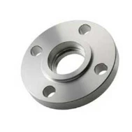
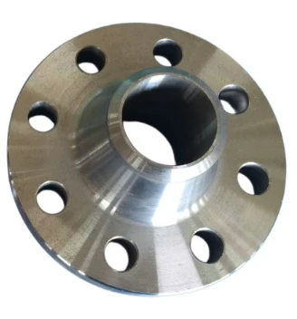
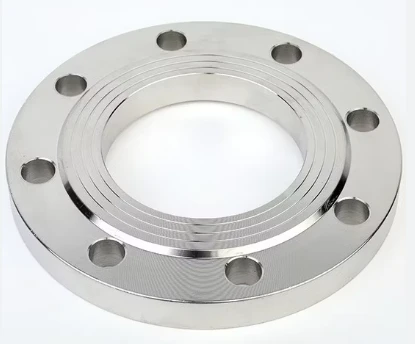
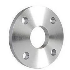
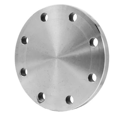
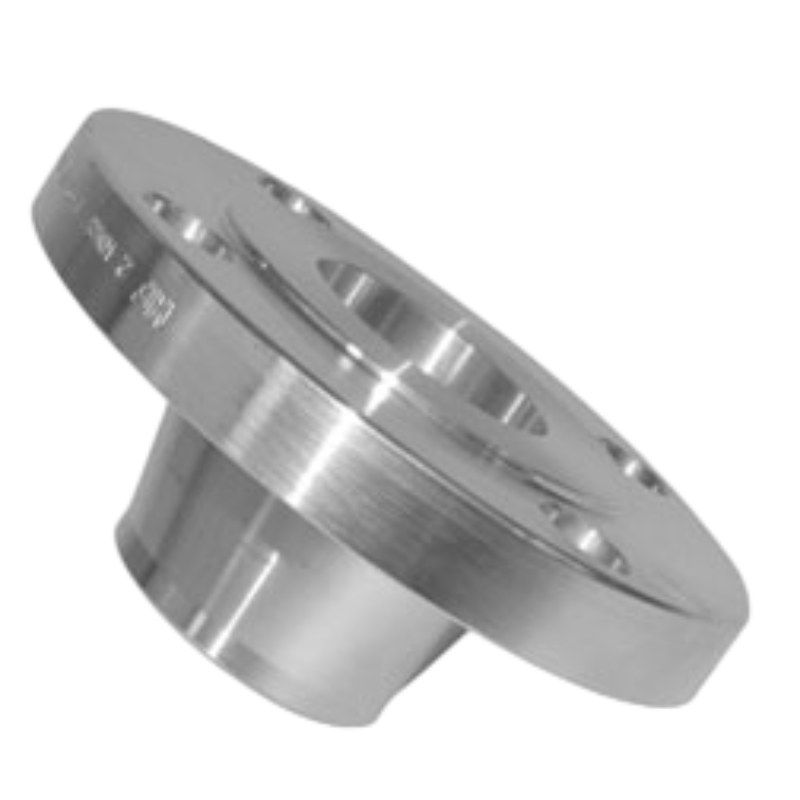
EN1092-1 FLANGE
EN 1092-1 flanges offer several key advantages that make them a preferred choice in various industries, including oil and gas, chemical processing, and power generation. One of the primary benefits of EN 1092-1 flanges is their adherence to stringent European standards, ensuring high-quality and reliable performance. This standardization guarantees compatibility across multiple applications and systems, simplifying the selection process for engineers and manufacturers. By meeting these standards, EN 1092-1 flanges provide a consistent level of safety, performance, and durability, which is crucial for operations requiring high-pressure or high-temperature handling.
Another advantage of EN 1092-1 flanges is their versatility in terms of material selection. These flanges are available in a wide range of materials, such as carbon steel, stainless steel, and alloy steel, allowing users to choose the most appropriate option based on the specific needs of their project. This flexibility ensures that the flange can withstand various environmental conditions, including corrosion, extreme temperatures, and chemical exposure, enhancing its longevity and reducing the risk of failure.
In addition, EN 1092-1 flanges are designed with precise dimensions and tolerances, ensuring a perfect fit for different pipe systems. This precision helps minimize the risk of leaks, which is especially important in applications involving hazardous or valuable materials. The flanges are also available in various pressure ratings, making them suitable for both low- and high-pressure systems.
Moreover, EN 1092-1 flanges are widely recognized for their ease of installation and maintenance. Their standardized dimensions make them compatible with a variety of piping systems, reducing downtime and ensuring seamless integration. This helps lower operational costs while enhancing system reliability, making EN 1092-1 flanges a cost-effective solution for long-term industrial use.
What Is EN1092 1 Flange Material?
In the world of engineering and manufacturing, the EN 1092 1 material plays a crucial role in ensuring the reliability and performance of piping systems. According to the European EN 1092 1 flange standard, this specification outlines the requirements for flanges used in pipelines and pressure vessels. Flanges are essential components that facilitate the connection between various sections of piping, offering a robust and leak-proof seal.
EN1092 1 flange materials can vary widely, depending on the application and environmental conditions. Common materials include carbon steel, stainless steel, and alloy steel. The choice of material is paramount as it determines the flange's strength, durability, and resistance to corrosion. For instance, stainless steel flanges are often preferred in corrosive environments due to their enhanced resistance to oxidation and rust, making them ideal for chemical processing and marine applications.
The EN1092 1 standard categorizes flanges based on their pressure-temperature ratings, which helps in selecting the appropriate flange material for specific operating conditions. Other critical factors to consider include the speed of installation, ease of maintenance, and compatibility with other system components, as the wrong choice can lead to failures and costly downtimes.
When sourcing EN1092 1 flange materials, it is vital to partner with suppliers who understand the unique specifications and standards required for your project. Quality assurance and compliance with the EN1092-1 standard are essential in guaranteeing that the flanges perform reliably under working conditions.
In conclusion, EN1092 1 flange material is a significant consideration for engineers and manufacturers in the design and implementation of effective piping systems. Selecting the right material not only ensures system integrity and safety but also promotes long-term operational efficiency.
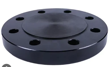
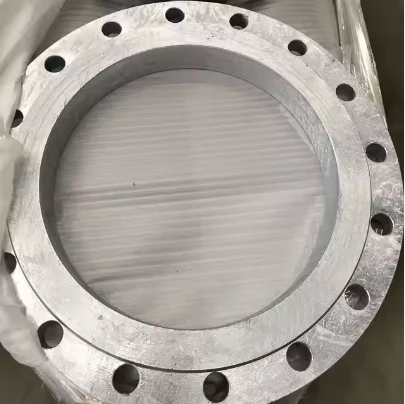
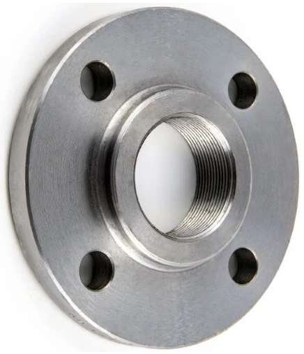
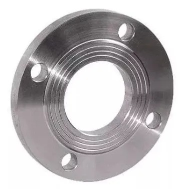
EN 1092 1 Flange Type
Key Features of EN1092 1 Flange
1. Design Variations: The EN1092 1 flange is available in various designs, including raised face, flat face, and ring type. Each design serves different operational requirements and helps in achieving the desired sealing effectiveness.
2. Material Composition: These flanges can be manufactured from various materials such as carbon steel, stainless steel, and alloy steel, offering versatility based on the application's needs. Selecting the right material is crucial for corrosion resistance and suitable performance under varying temperatures and pressures.
3. Pressure Ratings: EN1092 1 flanges come in numerous pressure ratings, allowing engineers to choose flanges that match the system’s operational pressure. This ensures safety and durability during operations.
4. Standards Compliance: The EN1092 1 flange adheres to international standards, guaranteeing a high level of quality and performance. Compliance means that flanges manufactured under this specification have undergone testing and validation to meet industry requirements.
Applications of EN1092 1 Flange
The EN1092 1 flange is popularly utilized in several industries, including:
- Oil and Gas: Used extensively in pipelines and equipment, ensuring safe and efficient fluid transport.
- Chemical Processing: Facilitating connections in reactors, pumps, and storage tanks, where leak prevention is paramount.
- Water Treatment: Employed in treatment plants for creating secure connections in piping systems.
Why Choose EN1092 1 Flange?
When designing or upgrading piping systems, the selection of the EN1092 1 flange offers several advantages:
Reliability: Its robust construction ensures reliable performance over time.
- Versatility: Available in various designs and materials to suit unique application needs.
- Cost-Effective: Investing in quality flanges can reduce maintenance costs and enhance system longevity.
EN 1092 1 Flange FAQs
Q1: What is the EN1092 1 Flange made of?
A1: The EN1092 1 Flange is crafted from high-quality carbon steel, stainless steel, or alloy steel, depending on your specific requirements. This ensures exceptional durability, resistance to corrosion, and resilience in high-pressure applications, making it suitable for various industrial uses.
Q2: What are the dimensions and pressure ratings available for the EN1092 1 Flange?
A2: The EN1092 1 Flange is available in various sizes and pressure ratings, ensuring compatibility with your piping system. Common dimensions range from DN10 to DN2000, and pressure ratings can be found in PN2.5 to PN40. You can find the exact sizing details in the product specifications section or contact us for more customized options.
Q3: Is the EN1092 1 Flange suitable for welding?
A3: Yes, the EN1092 1 Flange is designed for welding applications. The flange features a smooth, flat surface that allows for easy and secure welding to pipes and fittings, maintaining the integrity and performance of your systems while ensuring leak-free connections.
Q4: How do I know if the EN1092 1 Flange is compatible with my existing piping system?
A4: To determine compatibility, you will need to check the flange dimensions, materials, and pressure ratings of your existing piping system. The EN1092 1 Flange is designed to international standards, making it compatible with a wide range of systems. If you have further concerns, our expert team is available to assist you in ensuring a perfect fit.
Q5: What applications are suitable for the EN1092 1 Flange?
A5: The EN1092 1 Flange is versatile and ideal for various applications, including water supply systems, chemical processing, HVAC systems, and oil and gas transportation. Its robust design allows it to withstand harsh conditions, making it a reliable choice for both industrial and commercial use.
EN 1092-1:2007
DIMENSIONS OF PN6 FLANGES
| DN | Outside diameter |
Diameter of bolt circle |
Diameter of bolt hole |
Bolt number |
Outside diameter of neck A |
Bore diameters | Flange thickness | Chamfer | Wall thickness |
Collar Thickness |
Diameter of shoulder Gmax |
|||
| B, | B2 | C, | C2 | C1 | E | S | F | |||||||
| Flange type | ||||||||||||||
| 01.02.05.11.12.13 | 11 | 01 12 |
02 | 01 02 |
11 12.13 |
05 | 02 | 11 | 32 | 05 | ||||
| 10 | 75 | 50 | 11 | 4 | 17.2 | 18.0 | 21 | 12 | 12 | 12 | 3 | 2 | 10 | - |
| 15 | 80 | 55 | 11 | 4 | 21.3 | 22.0 | 25 | 12 | 12 | 12 | 3 | 2 | 10 | - |
| 20 | 90 | 65 | 11 | 4 | 26.9 | 27.5 | 31 | 14 | 14 | 14 | 4 | 2.3 | 10 | - |
| 25 | 100 | 75 | 11 | 4 | 33.7 | 34.5 | 38 | 14 | 14 | 14 | 4 | 2.6 | 10 | - |
| 32 | 120 | 90 | 14 | 4 | 42.4 | 43.5 | 46 | 16 | 14 | 14 | 5 | 2.6 | 10 | - |
| 40 | 130 | 100 | 14 | 4 | 48.3 | 49.5 | 53 | 16 | 14 | 14 | 5 | 2.6 | 10 | - |
| 50 | 140 | 110 | 14 | 4 | 60.3 | 61.5 | 65 | 16 | 14 | 14 | 5 | 2.9 | 12 | - |
| 65 | 160 | 130 | 14 | 4 | 76.1 | 77.5 | 81 | 16 | 14 | 14 | 6 | 2.9 | 12 | 55 |
| 80 | 190 | 150 | 18 | 4 | 88.9 | 90.5 | 94 | 18 | 16 | 16 | 6 | 3.2 | 12 | 70 |
| 100 | 210 | 170 | 18 | 4 | 114.3 | 116.0 | 120 | 18 | 16 | 16 | 6 | 3.6 | 14 | 90 |
| 125 | 240 | 200 | 18 | 8 | 139.7 | 141.5 | 145 | 20 | 18 | 18 | 6 | 4.0 | 14 | 115 |
| 150 | 265 | 225 | 18 | 8 | 168.3 | 170.5 | 174 | 20 | 18 | 18 | 6 | 4.5 | 14 | 140 |
| 200 | 320 | 280 | 18 | 8 | 219.1 | 221.5 | 226 | 22 | 20 | 20 | 6 | 6.3 | 16 | 190 |
| 250 | 375 | 335 | 18 | 12 | 273.0 | 276.5 | 281 | 24 | 22 | 22 | 8 | 6.3 | 18 | 235 |
| 300 | 440 | 395 | 22 | 12 | 323.9 | 327.5 | 333 | 24 | 22 | 22 | 8 | 7.1 | 18 | 285 |
| 350 | 490 | 445 | 22 | 12 | 355.6 | 359.5 | 365 | 26 | 22 | 22 | 8 | 7.1 | 18 | 330 |
| 400 | 540 | 495 | 22 | 16 | 406.4 | 411.0 | 416 | 28 | 22 | 22 | 8 | 7.1 | 20 | 380 |
| 450 | 595 | 550 | 22 | 16 | 457.0 | 462.0 | 467 | 30 | 22 | 24 | 8 | 7.1 | 20 | 425 |
| 500 | 645 | 600 | 22 | 20 | 508.0 | 513.5 | 519 | 30 | 24 | 24 | 8 | 7.1 | 22 | 475 |
| 600 | 755 | 705 | 26 | 20 | 610.0 | 616.5 | 622 | 32 | 30 | 30 | 8 | 7.1 | 22 | 575 |
| 700 | 860 | 810 | 26 | 24 | 711.0 | To be specifed by the purch aser |
721 | 40 | 30 | 40 | 4 | 8 | - | 670 |
| 800 | 975 | 920 | 30 | 24 | 813.0 | 824 | 44 | 30 | 44 | 4 | 8 | - | 770 | |
| 900 | 1075 | 1020 | 30 | 24 | 914.0 | 926 | 48 | 34 | 48 | 4 | 8 | - | 860 | |
| 1000 | 1175 | 1120 | 30 | 28 | 1016.0 | 1028 | 52 | 38 | 52 | 4 | 8 | - | 960 | |
| 1200 | 1405 | 1340 | 33 | 32 | 1219.0 | 1234 | 60 | 42 | 60 | 5 | 8.8 | - | 1160 | |
| DN | Raised face | Length | Neck diameters | Corner radii |
APPROXIMATE WEIGHT | ||||||||
| d, | 1 | H, | H2 | H3 | N | N2 | R, | ||||||
| Flange type | |||||||||||||
| 01.05.11.12.13 | 12 13 |
11 | 11 | 11 | 12 13 |
11 12.13 |
Type01 | Type02 | Type05 | Type11 | Type12 | ||
| 10 | 35 | 2 | 20 | 28 | 6 | 26 | 25 | 4 | 0.356 | 0.345 | 0.38 | 0.353 | 0.326 |
| 15 | 40 | 2 | 20 | 30 | 6 | 30 | 30 | 4 | 0.402 | 0.388 | 0.438 | 0.408 | 0.373 |
| 20 | 50 | 2 | 24 | 32 | 6 | 38 | 40 | 4 | 0.592 | 0.568 | 0.657 | 0.621 | 0.584 |
| 25 | 60 | 2 | 24 | 35 | 6 | 42 | 50 | 4 | 0.719 | 0.688 | 0.821 | 0.762 | 0.729 |
| 32 | 70 | 2 | 26 | 35 | 6 | 55 | 60 | 6 | 1.16 | 1.12 | 1.18 | 1.11 | 1.04 |
| 40 | 80 | 3 | 26 | 38 | 7 | 62 | 70 | 6 | 1.35 | 1.29 | 1.39 | 1.26 | 1.20 |
| 50 | 90 | 3 | 28 | 38 | 8 | 74 | 80 | 6 | 1.48 | 1.42 | 1.62 | 1.43 | 1.34 |
| 65 | 110 | 3 | 32 | 38 | 9 | 88 | 100 | 6 | 1.86 | 1.76 | 2.14 | 1.77 | 1.83 |
| 80 | 128 | 3 | 34 | 42 | 10 | 102 | 110 | 8 | 2.95 | 2.84 | 3.43 | 2.88 | 2.75 |
| 100 | 148 | 3 | 40 | 45 | 10 | 130 | 130 | 8 | 3.26 | 3.10 | 4.22 | 3.41 | 3.01 |
| 125 | 178 | 3 | 44 | 48 | 10 | 155 | 160 | 8 | 4.31 | 4.12 | 6.10 | 4.65 | 4.30 |
| 150 | 202 | 3 | 44 | 48 | 12 | 184 | 185 | 10 | 4.76 | 4.53 | 7.51 | 5.50 | 4.63 |
| 200 | 258 | 3 | 44 | 55 | 15 | 236 | 240 | 10 | 6.88 | 6.51 | 12.3 | 8.60 | 6.97 |
| 250 | 312 | 3 | 44 | 60 | 15 | 290 | 295 | 12 | 8.92 | 8.32 | 18.5 | 11.7 | 9.13 |
| 300 | 365 | 4 | 44 | 62 | 15 | 342 | 355 | 12 | 11.9 | 11.1 | 25.5 | 15.3 | 12.4 |
| 350 | 415 | 4 | - | 62 | 15 | 385 | - | 12 | 16.8 | 15.9 | 31.8 | 20.3 | - |
| 400 | 465 | 4 | - | 65 | 15 | 438 | - | 12 | 19.8 | 18.8 | 38.5 | 23.1 | - |
| 450 | 520 | 4 | - | 65 | 15 | 492 | - | 12 | 24.6 | 23.3 | 51.2 | 27.0 | - |
| 500 | 570 | 4 | - | 68 | 15 | 538 | - | 12 | 26.4 | 24.9 | 60.1 | 30.8 | - |
| 600 | 670 | 5 | - | 70 | 16 | 640 | - | 12 | 34.8 | 33.0 | 103 | 44.0 | - |
| 700 | 775 | 5 | - | 76 | 16 | 740 | - | 12 | - | - | 178 | 53.7 | - |
| 800 | 880 | 5 | - | 76 | 16 | 842 | - | 12 | - | - | 252 | 64.4 | - |
| 900 | 980 | 5 | - | 78 | 16 | 942 | - | 12 | - | - | 336 | 79.2 | - |
| 1000 | 1080 | 5 | - | 82 | 16 | 1045 | - | 16 | - | - | 435 | 98.6 | - |
| 1200 | 1295 | 5 | - | 104 | 20 | 1248 | - | 16 | - | - | 717 | 152 | - |
EN 1092-1:2007
DIMENSIONS OF PN10 FLANGES
| DN | Outside diameter |
Diameter of bolt circle |
Diameter of bolt hole |
Bolt number |
Outside diameter of nck A |
Bore diameters | Flange thickness | Chamfer | Wall thickness |
Collar Thickness |
Diameter of shoulder Gmax |
|||
| B, | B2 | C, | C2 | C | E | S | F | |||||||
| Flange type | ||||||||||||||
| 01.02.05.11.12.13 | 11 | 01 12 |
02 | 01 02 |
11 12.13 |
05 | 02 | 11 | 32 | 05 | ||||
| 10 | 90 | 60 | 14 | 4 | 17.2 | 18.0 | 21 | 14 | 16 | 16 | 3 | 2 | 12 | - |
| 15 | 95 | 65 | 14 | 4 | 21.3 | 22.0 | 25 | 14 | 16 | 16 | 3 | 2 | 12 | - |
| 20 | 105 | 75 | 14 | 4 | 26.9 | 27.5 | 31 | 16 | 18 | 18 | 4 | 2.3 | 14 | - |
| 25 | 115 | 85 | 14 | 4 | 33.7 | 34.5 | 38 | 16 | 18 | 18 | 4 | 2.6 | 14 | - |
| 32 | 140 | 100 | 18 | 4 | 42.4 | 43.5 | 47 | 18 | 18 | 18 | 5 | 2.6 | 14 | - |
| 40 | 150 | 110 | 18 | 4 | 48.3 | 49.5 | 53 | 18 | 18 | 18 | 5 | 2.6 | 14 | - |
| 50 | 165 | 125 | 18 | 4 | 60.3 | 61.5 | 65 | 20 | 18 | 18 | 5 | 2.9 | 16 | - |
| 65 | 185 | 145 | 18 | 8 | 76.1 | 77.5 | 81 | 20 | 18 | 18 | 6 | 2.9 | 16 | 55 |
| 80 | 200 | 160 | 18 | 8 | 88.9 | 90.5 | 94 | 20 | 20 | 20 | 6 | 3.2 | 16 | 70 |
| 100 | 220 | 180 | 18 | 0 | 114.3 | 116.0 | 120 | 22 | 20 | 20 | 6 | 3.6 | 18 | 90 |
| 125 | 250 | 210 | 18 | 8 | 139.7 | 141.5 | 145 | 22 | 22 | 22 | 6 | 4.0 | 18 | 115 |
| 150 | 285 | 240 | 22 | 8 | 168.3 | 170.5 | 174 | 24 | 22 | 22 | 6 | 4.5 | 20 | 140 |
| 200 | 340 | 295 | 22 | 8 | 219.1 | 221.5 | 226 | 24 | 24 | 24 | 6 | 6.3 | 20 | 190 |
| 250 | 395 | 350 | 22 | 12 | 273.0 | 276.5 | 281 | 26 | 26 | 26 | 8 | 6.3 | 22 | 235 |
| 300 | 445 | 400 | 22 | 12 | 323.9 | 327.5 | 333 | 26 | 26 | 26 | 8 | 7.1 | 22 | 285 |
| 350 | 505 | 460 | 22 | 16 | 355.6 | 359.5 | 365 | 30 | 26 | 26 | 8 | 7.1 | 22 | 330 |
| 400 | 565 | 515 | 26 | 16 | 406.4 | 411.0 | 416 | 32 | 26 | 26 | 8 | 7.1 | 24 | 380 |
| 450 | 615 | 565 | 26 | 20 | 457.0 | 462.0 | 467 | 36 | 28 | 28 | 8 | 7.1 | 24 | 425 |
| 500 | 670 | 620 | 26 | 20 | 508.0 | 513.5 | 519 | 38 | 28 | 28 | 8 | 7.1 | 26 | 475 |
| 600 | 780 | 725 | 30 | 20 | 610.0 | 616.5 | 622 | 42 | 30 | 34 | 8 | 8.0 | 26 | 575 |
| 700 | 895 | 840 | 30 | 24 | 711.0 | Tobe specifed bythe purch aser |
721 | 50 | 35 | 38 | 8 | 8.8 | - | 670 |
| 800 | 1015 | 950 | 33 | 24 | 813.0 | 824 | 56 | 38 | 48 | 8 | 8.8 | - | 770 | |
| 900 | 1115 | 1050 | 33 | 28 | 914.0 | 926 | 62 | 38 | 50 | 8 | 12.5 | - | 860 | |
| 1000 | 1230 | 1160 | 36 | 28 | 1016.0 | 1028 | 70 | 44 | 54 | 8 | 12.5 | - | 960 | |
| 1200 | 1455 | 1380 | 39 | 32 | 1219.0 | 1234 | 83 | 55 | 66 | 8 | 12.5 | - | 1160 | |
| DN | Raised face | Length | Neck diameters | Corner radii |
APPROXIMATE WEIGHT | ||||||||
| d, | 1 | H, | H2 | H3 | N, | N2 | R, | ||||||
| Flange type | |||||||||||||
| 01.05.11.12.13 | 12 13 |
11 | 11 | 11 | 12 13 |
11 12.13 |
Type01 | Type02 | Type05 | Type11 | Type12 | ||
| 10 | 40 | 2 | 22 | 35 | 6 | 28 | 30 | 4 | 0.604 | 0.591 | 0.722 | 0.678 | 0.646 |
| 15 | 45 | 2 | 22 | 38 | 6 | 32 | 35 | 4 | 0.670 | 0,654 | 0.813 | 0.768 | 0.722 |
| 20 | 58 | 2 | 26 | 40 | 6 | 40 | 45 | 4 | 0.936 | 0.909 | 1.14 | 1.09 | 1.04 |
| 25 | 68 | 2 | 28 | 40 | 6 | 46 | 52 | 4 | 1.11 | 1.08 | 1.38 | 1.30 | 1.25 |
| 32 | 78 | 2 | 30 | 42 | 6 | 56 | 60 | 6 | 1.82 | 1.77 | 2.03 | 1.91 | 1.81 |
| 40 | 88 | 3 | 32 | 45 | 7 | 64 | 70 | 6 | 2.08 | 2.02 | 2.35 | 2.15 | 2.06 |
| 50 | 102 | 3 | 28 | 45 | 8 | 74 | 84 | 6 | 2.73 | 2.52 | 2.88 | 2.53 | 2.39 |
| 65 | 122 | 3 | 32 | 45 | 10 | 92 | 104 | 6 | 3.16 | 3.05 | 3.51 | 3.03 | 2.97 |
| 80 | 138 | 3 | 34 | 50 | 10 | 105 | 118 | 6 | 3.79 | 3.48 | 4.61 | 3.92 | 3.78 |
| 100 | 158 | 3 | 40 | 52 | 12 | 131 | 140 | 8 | 4.39 | 4.20 | 5.65 | 4.62 | 4.38 |
| 125 | 188 | 3 | 44 | 55 | 12 | 156 | 168 | 8 | 5.41 | 5.21 | 8.13 | 6.30 | 6.07 |
| 150 | 212 | 3 | 44 | 55 | 12 | 184 | 195 | 10 | 7.14 | 6.89 | 10.5 | 7.81 | 7.24 |
| 200 | 268 | 3 | 44 | 62 | 16 | 234 | 246 | 10 | 9.27 | 8.87 | 16.5 | 11.6 | 10.1 |
| 250 | 320 | 3 | 46 | 68 | 16 | 292 | 298 | 12 | 11.8 | 11.2 | 24.1 | 15.8 | 12.8 |
| 300 | 370 | 4 | 46 | 68 | 16 | 342 | 350 | 12 | 13.6 | 12.8 | 30.8 | 18.3 | 14.5 |
| 350 | 430 | 4 | 53 | 68 | 16 | 385 | 400 | 12 | 20.4 | 19.4 | 39.6 | 25.3 | 22.7 |
| 400 | 482 | 4 | 57 | 72 | 16 | 440 | 456 | 12 | 27.5 | 26.4 | 49.4 | 30.6 | 28.0 |
| 450 | 532 | 4 | 63 | 72 | 16 | 488 | 502 | 12 | 33.6 | 32.2 | 63 | 35.1 | 32.3 |
| 500 | 585 | 4 | 67 | 75 | 16 | 542 | 559 | 12 | 40.2 | 38.5 | 75.2 | 40.5 | 38.7 |
| 600 | 685 | 5 | 75 | 82 | 18 | 642 | 658 | 12 | 54.5 | 52.2 | 124 | 52.9 | 48.9 |
| 700 | 800 | 5 | - | 85 | 18 | 746 | - | 12 | - | 79.4 | 183 | 75.8 | - |
| 800 | 905 | 5 | - | 96 | 18 | 850 | - | 12 | - | 112 | 297 | 102 | - |
| 900 | 1005 | 5 | - | 99 | 20 | 950 | - | 12 | - | 135 | 374 | 121 | - |
| 1000 | 1110 | 5 | - | 105 | 20 | 1052 | - | 16 | - | 180 | 492 | 161 | - |
| 1200 | 1330 | 5 | - | 132 | 25 | 1256 | - | 16 | - | 278 | 842 | 258 | - |
EN 1092-1:2007
DIMENSIONS OF PN16 FLANGES
| DN | Outside diameter |
Diameter of bolt circle |
Diameter of bolt hole |
Bolt number |
Outside diameter of neck A |
Bore diameters | Flange thickness | Chamfer | Wall thickness |
Collar Thickness |
Diameter of shoulder Gmax |
|||
| B, | B2 | C, | C2 | C | E | S | F | |||||||
| Flange type | ||||||||||||||
| 01.02.05.11.12.13 | 11 | 01 12 |
02 | 01 02 |
11 12.13 |
05 | 02 | 11 | 32 | 05 | ||||
| 10 | 90 | 60 | 14 | 4 | 17.2 | 18.0 | 21 | 14 | 16 | 16 | 3 | 2 | 12 | - |
| 15 | 95 | 65 | 14 | 4 | 21.3 | 22.0 | 25 | 14 | 16 | 16 | 3 | 2 | 12 | - |
| 20 | 105 | 75 | 14 | 4 | 26.9 | 27.5 | 31 | 16 | 18 | 18 | 4 | 2.3 | 14 | - |
| 25 | 115 | 85 | 14 | 4 | 33.7 | 34.5 | 38 | 16 | 18 | 18 | 4 | 2.6 | 14 | - |
| 32 | 140 | 100 | 18 | 4 | 42.4 | 43.5 | 47 | 18 | 18 | 18 | 5 | 2.6 | 14 | - |
| 40 | 150 | 110 | 18 | 4 | 48.3 | 49.5 | 53 | 18 | 18 | 18 | 5 | 2.6 | 14 | - |
| 50 | 165 | 125 | 18 | 4 | 60.3 | 61.5 | 65 | 20 | 18 | 18 | 5 | 2.9 | 16 | - |
| 65 | 185 | 145 | 18 | 8 | 76.1 | 77.5 | 81 | 20 | 18 | 18 | 6 | 2.9 | 16 | 55 |
| 80 | 200 | 160 | 18 | 8 | 88.9 | 90.5 | 94 | 20 | 20 | 20 | 6 | 3.2 | 16 | 70 |
| 100 | 220 | 180 | 18 | 8 | 114.3 | 116.0 | 120 | 22 | 20 | 20 | 6 | 3.6 | 18 | 90 |
| 125 | 250 | 210 | 18 | 8 | 139.7 | 141.5 | 145 | 22 | 22 | 22 | 6 | 4.0 | 18 | 115 |
| 150 | 285 | 240 | 22 | 8 | 168.3 | 170.5 | 174 | 24 | 22 | 22 | 6 | 4.5 | 20 | 140 |
| 200 | 340 | 295 | 22 | 12 | 219.1 | 221.5 | 226 | 26 | 24 | 24 | 6 | 6.3 | 20 | 190 |
| 250 | 405 | 355 | 26 | 12 | 273.0 | 276.5 | 281 | 29 | 26 | 26 | 8 | 6.3 | 22 | 235 |
| 300 | 460 | 410 | 26 | 12 | 323.9 | 327.5 | 333 | 32 | 28 | 28 | 8 | 7.1 | 24 | 285 |
| 350 | 520 | 470 | 26 | 16 | 355.6 | 359.5 | 365 | 35 | 30 | 30 | 8 | 8.0 | 26 | 330 |
| 400 | 580 | 525 | 30 | 16 | 406.4 | 411.0 | 416 | 38 | 32 | 32 | 8 | 8.0 | 28 | 380 |
| 450 | 640 | 585 | 30 | 20 | 457.0 | 462.0 | 467 | 42 | 34 | 40 | 8 | 8.8 | 30 | 425 |
| 500 | 715 | 650 | 33 | 20 | 508.0 | 513.5 | 519 | 46 | 36 | 44 | 8 | 8.8 | 32 | 475 |
| 600 | 840 | 770 | 36 | 20 | 610.0 | 616.5 | 622 | 55 | 40 | 54 | 8 | 10.0 | 32 | 575 |
| 700 | 910 | 840 | 36 | 24 | 711.0 | Tobe specfied by the purch aser |
721 | 63 | 40 | 58 | 8 | 10.0 | - | 670 |
| 800 | 1025 | 950 | 39 | 24 | 813.0 | 824 | 74 | 41 | 62 | 8 | 12.5 | - | 770 | |
| 900 | 1125 | 1050 | 39 | 28 | 914.0 | 926 | 82 | 48 | 64 | 8 | 12.5 | - | 860 | |
| 1000 | 1255 | 1170 | 42 | 28 | 1016.0 | 1030 | 90 | 59 | 68 | 8 | 12.5 | - | 960 | |
| DN | Raised face | Length | Neck diameters | Corner radii |
APPROXIMATE WEIGHT | ||||||||
| d, | 1 | H, | H2 | H3 | N, | N2 | R, | ||||||
| Flange type | |||||||||||||
| 01.05.11.12.13 | 12 13 |
11 | 11 | 11 | 12 13 |
11 12.13 |
Type01 | Type02 | Type05 | Type11 | Type12 | ||
| 10 | 40 | 2 | 22 | 35 | 6 | 28 | 30 | 4 | 0.604 | 0.591 | 0.722 | 0.678 | 0.646 |
| 15 | 45 | 2 | 22 | 38 | 6 | 32 | 35 | 4 | 0.670 | 0.654 | 0.813 | 0.768 | 0.722 |
| 20 | 58 | 2 | 26 | 40 | 6 | 40 | 45 | 4 | 0.936 | 0.909 | 1.14 | 1.09 | 1.04 |
| 25 | 68 | 2 | 28 | 40 | 6 | 46 | 52 | 4 | 1.11 | 1.08 | 1.38 | 1.3 | 1.25 |
| 32 | 78 | 2 | 30 | 42 | 6 | 56 | 60 | 6 | 1.82 | 1.77 | 2.03 | 1.91 | 1.81 |
| 40 | 88 | 3 | 32 | 45 | 7 | 64 | 70 | 6 | 2.08 | 2.02 | 2.35 | 2.15 | 2.06 |
| 50 | 102 | 3 | 28 | 45 | 8 | 74 | 84 | 6 | 2.73 | 2.52 | 2.88 | 2.53 | 2.39 |
| 65 | 122 | 3 | 32 | 45 | 10 | 92 | 104 | 6 | 3.16 | 3.05 | 3.51 | 3.03 | 2.97 |
| 80 | 138 | 3 | 34 | 50 | 10 | 105 | 118 | 6 | 3.79 | 3.48 | 4.61 | 3.92 | 3.78 |
| 100 | 158 | 3 | 40 | 52 | 12 | 131 | 140 | 8 | 4.39 | 4.20 | 5.65 | 4.62 | 4.38 |
| 125 | 188 | 3 | 44 | 55 | 12 | 156 | 168 | 8 | 5.41 | 5.21 | 8.13 | 6.30 | 6.07 |
| 150 | 212 | 3 | 44 | 55 | 12 | 184 | 195 | 10 | 7.14 | 6.89 | 10.5 | 7.81 | 7.24 |
| 200 | 268 | 3 | 44 | 62 | 16 | 235 | 246 | 10 | 9.73 | 9.31 | 16.2 | 11.5 | 9.8 |
| 250 | 320 | 3 | 46 | 70 | 16 | 292 | 298 | 12 | 14.2 | 13.5 | 25.0 | 16.70 | 13.6 |
| 300 | 378 | 4 | 46 | 78 | 16 | 344 | 350 | 12 | 19 | 18.0 | 35.1 | 22.1 | 17.2 |
| 350 | 438 | 4 | 57 | 82 | 16 | 390 | 400 | 12 | 28.2 | 27.0 | 48.0 | 32.8 | 27.9 |
| 400 | 490 | 4 | 63 | 85 | 16 | 445 | 456 | 12 | 35.9 | 34.6 | 63.5 | 41.1 | 35.7 |
| 450 | 550 | 4 | 68 | 83 | 16 | 490 | 502 | 12 | 46.1 | 44.6 | 96.6 | 50.6 | 45.0 |
| 500 | 610 | 4 | 73 | 84 | 16 | 548 | 559 | 12 | 64.0 | 62.0 | 133 | 66.2 | 60.4 |
| 600 | 725 | 5 | 83 | 88 | 18 | 670 | 658 | 12 | 102 | 98.8 | 226 | 104 | 94 |
| 700 | 795 | 5 | 83 | 104 | 18 | 755 | 760 | 12 | - | 107 | 285 | 96.5 | - |
| 800 | 900 | 5 | 90 | 108 | 20 | 855 | 864 | 12 | - | 152 | 388 | 122 | - |
| 900 | 1000 | 5 | 94 | 118 | 20 | 955 | 968 | 12 | - | 184 | 483 | 155 | - |
| 1000 | 1115 | 5 | 100 | 137 | 22 | 1058 | 1072 | 16 | - | 257 | 640 | 233 | - |
EN 1092-1:2007
DIMENSIONS OF PN25 FLANGES
| DN | Outside diameter |
Diameter of bolt circle |
Diameter of bolt hole |
Bolt number |
Outside diameter of neck A |
Bore diameters | Flange thickness | Chamfer | Wall thickness |
Collar Thickness |
Diameter shoulder Gmax |
|||
| B, | B, | C, | C2 | C1 | E | S | F | |||||||
| Flange type | ||||||||||||||
| 01.02.05.11.12.13 | 11 | 01 12 |
02 | 01 02 |
11 12.13 |
05 | 02 | 11 | 32 | 05 | ||||
| 10 | 90 | 60 | 14 | 4 | 17.2 | 18.0 | 21 | 14 | 16 | 16 | 3 | 2.0 | 12 | - |
| 15 | 95 | 65 | 14 | 4 | 21.3 | 22.0 | 25 | 14 | 16 | 16 | 3 | 2.0 | 12 | - |
| 20 | 105 | 75 | 14 | 4 | 26.9 | 27.5 | 31 | 16 | 18 | 18 | 4 | 2.3 | 14 | - |
| 25 | 115 | 85 | 14 | 4 | 33.7 | 34.5 | 38 | 16 | 18 | 18 | 4 | 2.6 | 14 | - |
| 32 | 140 | 100 | 18 | 4 | 42.4 | 43.5 | 47 | 18 | 18 | 18 | 5 | 2.6 | 14 | - |
| 40 | 150 | 110 | 18 | 4 | 48.3 | 49.5 | 53 | 18 | 18 | 18 | 5 | 2.6 | 14 | - |
| 50 | 165 | 125 | 18 | 4 | 60.3 | 61.5 | 65 | 20 | 20 | 20 | 5 | 2.9 | 16 | - |
| 65 | 185 | 145 | 18 | 8 | 76.1 | 77.5 | 81 | 22 | 22 | 22 | 6 | 2.9 | 16 | 55 |
| 80 | 200 | 160 | 18 | 8 | 88.9 | 90.5 | 94 | 24 | 24 | 24 | 6 | 3.2 | 18 | 70 |
| 100 | 235 | 190 | 22 | 8 | 114.3 | 116.0 | 120 | 26 | 24 | 24 | 6 | 3.6 | 20 | 90 |
| 125 | 270 | 220 | 26 | 8 | 139.7 | 141.5 | 145 | 28 | 26 | 26 | 6 | 4.0 | 22 | 115 |
| 150 | 300 | 250 | 26 | 8 | 168.3 | 170.5 | 174 | 30 | 28 | 28 | 6 | 4.5 | 24 | 140 |
| 200 | 360 | 310 | 26 | 12 | 219.1 | 221.5 | 226 | 32 | 30 | 30 | 6 | 6.3 | 26 | 190 |
| 250 | 425 | 370 | 30 | 12 | 273.0 | 276.5 | 281 | 35 | 32 | 32 | 8 | 7.1 | 26 | 235 |
| 300 | 485 | 430 | 30 | 16 | 323.9 | 327.5 | 333 | 38 | 34 | 34 | 8 | 8.0 | 28 | 285 |
| 350 | 555 | 490 | 33 | 16 | 355.6 | 359.5 | 365 | 42 | 38 | 38 | 8 | 8.0 | 32 | 332 |
| 400 | 620 | 550 | 36 | 16 | 406.4 | 411.0 | 416 | 48 | 40 | 40 | 8 | 8.8 | 34 | 380 |
| 450 | 670 | 600 | 36 | 20 | 457.0 | 462.0 | 467 | 54 | 46 | 50 | 8 | 8.8 | 36 | 425 |
| 500 | 730 | 660 | 36 | 20 | 508.0 | 513.5 | 519 | 58 | 48 | 51 | 8 | 10.0 | 38 | 475 |
| 600 | 845 | 770 | 39 | 20 | 610.0 | 616.5 | 622 | 68 | 48 | 66 | 8 | 12.5 | 40 | 575 |
| DN | Raised face | Length | Neck diameters | Corner radii |
APPROXIMATE WEIGHT | ||||||||
| d, | 1 | H, | H2 | H3 | N, | N2 | R, | ||||||
| Flange type | |||||||||||||
| 01.05.11.12.13 | 12 13 |
11 | 11 | 11 | 12 13 |
11 12.13 |
Type01 | Type02 | Type05 | Type11 | Type12 | ||
| 10 | 40 | 2 | 22 | 35 | 6 | 28 | 30 | 4 | 0.604 | 0.591 | 0.722 | 0.678 | 0.646 |
| 15 | 45 | 2 | 22 | 38 | 6 | 32 | 35 | 4 | 0.670 | 0.654 | 0.813 | 0.768 | 0.722 |
| 20 | 58 | 2 | 26 | 40 | 6 | 40 | 45 | 4 | 0.936 | 0.909 | 1.14 | 1.09 | 1.04 |
| 25 | 68 | 2 | 28 | 40 | 6 | 46 | 52 | 4 | 1.11 | 1.08 | 1.38 | 1.3 | 1.25 |
| 32 | 78 | 2 | 30 | 42 | 6 | 56 | 60 | 6 | 1.82 | 1.77 | 2.03 | 1.91 | 1.81 |
| 40 | 88 | 3 | 32 | 45 | 7 | 64 | 70 | 6 | 2.08 | 2.02 | 2.35 | 2.15 | 2.06 |
| 50 | 102 | 3 | 34 | 48 | 8 | 75 | 84 | 6 | 2.73 | 2.65 | 3.20 | 2.85 | 2.74 |
| 65 | 122 | 3 | 38 | 52 | 10 | 90 | 104 | 6 | 3.48 | 3.36 | 4.29 | 3.68 | 3.65 |
| 80 | 138 | 3 | 40 | 58 | 12 | 105 | 118 | 8 | 4.32 | 4.18 | 5.54 | 4.78 | 4.59 |
| 100 | 162 | 3 | 44 | 65 | 12 | 134 | 145 | 8 | 6.07 | 5.87 | 7.60 | 6.46 | 6.1 |
| 125 | 188 | 3 | 48 | 68 | 12 | 162 | 170 | 8 | 8.19 | 7.95 | 10.8 | 8.86 | 8.22 |
| 150 | 218 | 3 | 52 | 75 | 12 | 192 | 200 | 10 | 10.3 | 9.97 | 14.6 | 11.7 | 10.6 |
| 200 | 278 | 3 | 52 | 80 | 16 | 244 | 256 | 10 | 14.3 | 13.8 | 22.5 | 17.1 | 14.9 |
| 250 | 335 | 3 | 60 | 88 | 18 | 298 | 310 | 12 | 20.1 | 19.4 | 33.5 | 24.3 | 20.9 |
| 300 | 395 | 4 | 67 | 92 | 18 | 352 | 364 | 12 | 26.6 | 25.5 | 46.3 | 31.8 | 27.3 |
| 350 | 450 | 4 | 72 | 100 | 20 | 398 | 418 | 12 | 41.8 | 40.5 | 68.1 | 48.8 | 45.1 |
| 400 | 505 | 4 | 78 | 110 | 20 | 452 | 472 | 12 | 57.6 | 56.1 | 89.7 | 63.3 | 57.7 |
| 450 | 555 | 4 | 84 | 110 | 20 | 500 | 520 | 12 | 69.8 | 67.8 | 130 | 76 | 69.6 |
| 500 | 615 | 4 | 90 | 125 | 20 | 558 | 580 | 12 | 87.0 | 84.6 | 159 | 97 | 87 |
| 600 | 720 | 5 | 100 | 125 | 20 | 660 | 684 | 12 | 127 | 124 | 278 | 121 | 111 |
EN 1092-1:2007
DIMENSIONS OF PN40 FLANGES
| DN | Outside diameter |
Diameter of bolt circle |
Diameter of bolt hole |
Bolt number |
Outside diameter of neck A |
Bore diameters | Flange thickness | Chamfer | Wall thickness |
Collar Thickness |
Diameter of shoulder Gmax |
|||
| B, | B2 | C, | C1 | C1 | E | S | F | |||||||
| Flange type | ||||||||||||||
| 01.02.05.11.12.13 | 11 | 01 12 |
02 | 01 02 |
11 12.13 |
05 | 02 | 11 | 32 | 05 | ||||
| 10 | 90 | 60 | 14 | 4 | 17.2 | 18.0 | 21 | 14 | 16 | 16 | 3 | 2.0 | 12 | - |
| 15 | 95 | 65 | 14 | 4 | 21.3 | 22.0 | 25 | 14 | 16 | 16 | 3 | 2.0 | 12 | - |
| 20 | 105 | 75 | 14 | 4 | 26.9 | 27.5 | 31 | 16 | 18 | 18 | 4 | 2.3 | 14 | - |
| 25 | 115 | 85 | 14 | 4 | 33.7 | 34.5 | 38 | 16 | 18 | 18 | 4 | 2.6 | 14 | - |
| 32 | 140 | 100 | 18 | 4 | 42.4 | 43.5 | 47 | 18 | 18 | 18 | 5 | 2.6 | 14 | - |
| 40 | 150 | 110 | 18 | 4 | 48.3 | 49.5 | 53 | 18 | 18 | 18 | 5 | 2.6 | 14 | - |
| 50 | 165 | 125 | 18 | 4 | 60.3 | 61.5 | 65 | 20 | 20 | 20 | 5 | 2.9 | 16 | - |
| 65 | 185 | 145 | 18 | 8 | 76.1 | 77.5 | 81 | 22 | 22 | 22 | 6 | 2.9 | 16 | 55 |
| 80 | 200 | 160 | 18 | 8 | 88.9 | 90.5 | 94 | 24 | 24 | 24 | 6 | 3.2 | 18 | 70 |
| 100 | 235 | 190 | 22 | 8 | 114.3 | 116.0 | 120 | 26 | 24 | 24 | 6 | 3.6 | 20 | 90 |
| 125 | 270 | 220 | 26 | 8 | 139.7 | 141.5 | 145 | 28 | 26 | 26 | 6 | 4.0 | 22 | 115 |
| 150 | 300 | 250 | 26 | 8 | 168.3 | 170.5 | 174 | 30 | 28 | 28 | 6 | 4.5 | 24 | 140 |
| 200 | 375 | 320 | 30 | 12 | 219.1 | 221.5 | 226 | 36 | 34 | 36 | 6 | 6.3 | 28 | 190 |
| 250 | 450 | 385 | 33 | 12 | 273.0 | 276.5 | 281 | 42 | 38 | 38 | 8 | 7.1 | 30 | 235 |
| 300 | 515 | 450 | 33 | 16 | 323.9 | 327.5 | 333 | 52 | 42 | 42 | 8 | 8.0 | 34 | 285 |
| 350 | 580 | 510 | 36 | 16 | 355.6 | 359.5 | 365 | 58 | 46 | 46 | 8 | 8.8 | 36 | 330 |
| 400 | 660 | 585 | 39 | 16 | 406.4 | 411.0 | 416 | 65 | 50 | 50 | 8 | 11.0 | 42 | 380 |
| 450 | 685 | 610 | 39 | 20 | 457.0 | 462.0 | 467 | To be specified by the purchaser |
57 | 57 | 8 | 12.5 | 46 | 425 |
| 500 | 755 | 670 | 42 | 20 | 508.0 | 513.5 | 519 | 57 | 57 | 8 | 14.2 | 50 | 475 | |
| 600 | 890 | 795 | 48 | 20 | 610.0 | 616.5 | 622 | 72 | 72 | 8 | 16.0 | 54 | 575 | |
| DN | Raised face | Length | Neck diameters | Corer radi |
APPROXIMATE WEIGHT | ||||||||
| d, | 1. | H, | H2 | H3 | N, | N2 | R, | ||||||
| Flange type | |||||||||||||
| 01.05.11.12.13 | 12 13 |
11 | 11 | 11 | 12 13 |
11 12.13 |
Type01 | Type02 | Type05 | Type11 | Type12 | ||
| 10 | 40 | 2 | 22 | 35 | 6 | 28 | 30 | 4 | 0.604 | 0.591 | 0.722 | 0.678 | 0.646 |
| 15 | 45 | 2 | 22 | 38 | 6 | 32 | 35 | 4 | 0.67 | 0.654 | 0.813 | 0.768 | 0.722 |
| 20 | 58 | 2 | 26 | 40 | 6 | 40 | 45 | 4 | 0.936 | 0.909 | 1.14 | 1.09 | 1.04 |
| 25 | 68 | 2 | 28 | 40 | 6 | 46 | 52 | 4 | 1.11 | 1.08 | 1.38 | 1.30 | 1.25 |
| 32 | 78 | 2 | 30 | 42 | 6 | 56 | 60 | 6 | 1.82 | 1.77 | 2.03 | 1.91 | 1.81 |
| 40 | 88 | 3 | 32 | 45 | 7 | 64 | 70 | 6 | 2.08 | 2.02 | 2.35 | 2.15 | 2.06 |
| 50 | 102 | 3 | 34 | 48 | 8 | 75 | 84 | 6 | 2.73 | 2.65 | 3.20 | 2.85 | 2.74 |
| 65 | 122 | 3 | 38 | 52 | 10 | 90 | 104 | 6 | 3.48 | 3.36 | 4.29 | 3.68 | 3.65 |
| 80 | 138 | 3 | 40 | 58 | 12 | 105 | 118 | 8 | 4.32 | 4.18 | 5.54 | 4.78 | 4.59 |
| 100 | 162 | 3 | 44 | 65 | 12 | 134 | 145 | 8 | 6.07 | 5.87 | 7.60 | 6.46 | 6.10 |
| 125 | 188 | 3 | 48 | 68 | 12 | 162 | 170 | 8 | 8.19 | 7.95 | 10.8 | 8.86 | 8.22 |
| 150 | 218 | 3 | 52 | 75 | 12 | 192 | 200 | 10 | 10.3 | 9.97 | 14.6 | 11.7 | 10.6 |
| 200 | 285 | 3 | 52 | 88 | 16 | 244 | 260 | 10 | 17.9 | 17.4 | 28.8 | 21.0 | 18.3 |
| 250 | 345 | 3 | 60 | 105 | 18 | 306 | 312 | 12 | 29.3 | 28.4 | 44.4 | 34.2 | 28.3 |
| 300 | 410 | 4 | 67 | 115 | 18 | 362 | 380 | 12 | 45.1 | 43.6 | 64.2 | 47.6 | 40.4 |
| 350 | 465 | 4 | 72 | 125 | 20 | 408 | 424 | 12 | 66.7 | 64.9 | 89.5 | 69.3 | 58.8 |
| 400 | 535 | 4 | 78 | 135 | 20 | 462 | 478 | 12 | 97.1 | 95.1 | 127 | 98 | 82.1 |
| 450 | 560 | 4 | 84 | 135 | 20 | 500 | 522 | 12 | - | - | 154 | 105 | 86.2 |
| 500 | 615 | 4 | 90 | 140 | 20 | 562 | 576 | 12 | - | - | 188 | 130 | 105 |
| 600 | 735 | 5 | 100 | 150 | 20 | 666 | 686 | 12 | - | - | 331 | 209 | 172 |
